Honeywell HPF24S8 Installation Instructions - Page 14
General
 |
View all Honeywell HPF24S8 manuals
Add to My Manuals
Save this manual to your list of manuals |
Page 14 highlights
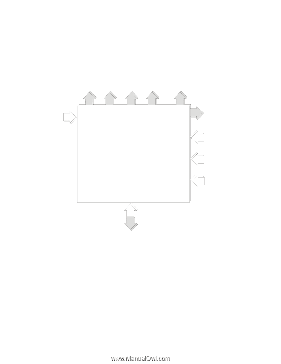
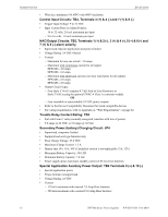
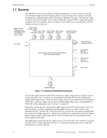
System Overview General 1.7 General The HPF24S may be used in a number of different applications. It may be used as a remotelymounted power supply and battery charger where it can provide up to four coded or noncoded, synchronized or nonsynchronized NACs (Notification Appliance Circuits). Alternatively, output #4 can be used as a door holder circuit which will provide a steady 24 VDC output until an alarm condition or AC fail condition causes it to drop to 0 VDC following a 10 second delay. All four outputs can also provide power. Note: All NAC outputs can be converted to Style Z with ZNAC-4 option module Style Y NAC or Door Holder Power Style Y NAC Output #4 Output #3 Style Y NAC Output #2 Style Y NAC Output #1 HPF24S Trouble Contact Output AC Power Input/Output Functions are Programmable by SW1 DIP Switch Settings 24 VDC Specific Application Power NAC Control Input #2 (from FACP) NAC Control Input #1 (from FACP) Sync. Input 24fsblok.wmf Battery Charger Figure 1.2 Simplified HPF24S Block Diagram One possible application for the HPF24S remote power supply utilizes the NAC repeater feature. In this application, one or two NACs are connected from the main FACP to the remote power supply control input circuits. When the control input circuits are activated by the reverse polarity of the NACs, the power supply will activate its corresponding output circuits as programmed by SW1 DIP switch configuration (refer to Table 3.1 on page 21). During the inactive state, the remote power supply supervises its NAC field wiring for short and open conditions. If a fault is detected, the power supply will enter a trouble condition and illuminate the NAC Trouble LED. When the NACs are activated, the supervision is disabled and the circuits are no longer supervised. Supervision of other power supply faults such as low battery, battery charger trouble, ground fault and AC loss will continue and may be monitored via the power supply trouble relay. If an application requires that all four outputs activate at the same time, only one NAC is required from the FACP. For this application, the NAC is connected to control input circuit #1 and SW1 DIP switch is set for this operation. 14 HPF24S Series Power Supplies - P/N 52751:D3 5/11/2010
-
 1
1 -
2
-
3
-
4
-
5
-
6
-
7
-
8
-
 9
9 -
 10
10 -
 11
11 -
 12
12 -
 13
13 -
 14
14 -
 15
15 -
 16
16 -
 17
17 -
 18
18 -
 19
19 -
20
-
21
-
22
-
23
-
24
-
25
-
26
-
27
-
28
-
29
-
30
-
31
-
32
-
33
-
34
-
35
-
36
-
37
-
38
-
39
-
40
-
41
-
42
-
43
-
44
-
45
-
46
-
47
-
48
-
49
-
50
-
51
-
52
 |
 |