Honeywell HPF24S8 Installation Instructions - Page 35
Master FACP With Slave HPF24S Power Supply
 |
View all Honeywell HPF24S8 manuals
Add to My Manuals
Save this manual to your list of manuals |
Page 35 highlights
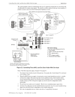
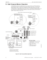
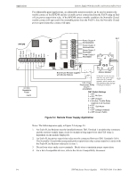
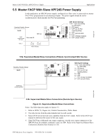
Master FACP With Slave HPF24S Power Supply Applications 5.5 Master FACP With Slave HPF24S Power Supply In this application, an HPF24S power supply, configured as a Slave unit, is connected to a master FACP NAC programmed for synchronized output. The power supply should be set for synchronization which matches the FACP programming. Standby Polarity Shown HPF24S See note #3. SW1 Switch Settings 1 & 2 = sync (any setting but OFF/OFF) 3 = ON (slave) 4 = OFF (no AC Fail reporting delay) 5 6 = = OFF OFF general alarm 7 = OFF (charger enabled) 8 = OFF (circuit 4 NAC) 24fsapp1.wmf Horn/Strobes 5.5a: Supervised Master/Slave Connections (Filtered, Synchronized NAC Source) Standby Polarity Shown SW1 Switch Settings 1 & 2 = sync (any setting but OFF/OFF) 3 = ON (slave) 4 = OFF (no AC Fail reporting delay) 5 = OFF 6 = OFF 7 = OFF (charger enabled) 8 = OFF (circuit 4 NAC) 24fsapp1b.wmf 5.5b: Supervised Master/Slave Connections (Remote Sync Source) Figure 5.5 Supervised Master/Slave Connections Notes: The following notes apply to Figures 5.5. 1. Refer to NFPA 72, Chapter 4-4, Visible Characteristics, Public Mode. 2. Use only devices from the same manufacturer in each system. 3. Some FACPs do not provide sync capability from the NAC output. Refer to the FACP user manual to determine the source of the sync signal. 4. If the FACP has a dedicated sync output connector, wire the sync output connnector to the HPF24S Sync In terminals, terminals 1 and 2 on TB4. Refer to the Supervised Master/Slave Connections (Remote Sync Source) in 5.5b. HPF24S Series Power Supplies - P/N 52751:D3 5/11/2010 35
-
 1
1 -
2
-
3
-
4
-
5
-
6
-
7
-
8
-
9
-
10
-
11
-
12
-
13
-
14
-
15
-
16
-
17
-
18
-
19
-
20
-
21
-
22
-
23
-
24
-
25
-
26
-
27
-
28
-
29
-
 30
30 -
 31
31 -
 32
32 -
 33
33 -
 34
34 -
 35
35 -
 36
36 -
 37
37 -
 38
38 -
 39
39 -
 40
40 -
41
-
42
-
43
-
44
-
45
-
46
-
47
-
48
-
49
-
50
-
51
-
52
 |
 |
