Honeywell HPF24S8 Installation Instructions - Page 34
Remote Power Supply Application
 |
View all Honeywell HPF24S8 manuals
Add to My Manuals
Save this manual to your list of manuals |
Page 34 highlights
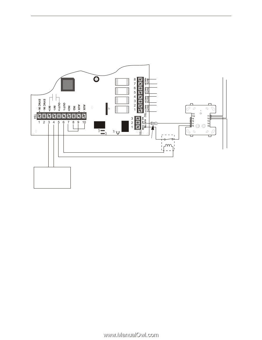
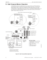
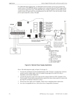
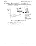
Applications Remote Supply With Resettable and Nonresettable Power For addressable panel applications, an addressable monitor module can be used to monitor the trouble contact of the HPF24S and the resettable power connection from the FACP using an Endof-Line power supervision relay. If the HPF24S enters a trouble condition, the Normally Closed trouble contact will open and if the resettable power from the FACP is lost, the Normally Closed power supervision relay contact will open. HPF24S SLC Power Output 4 Nonresettable Power Output 3 Nonresettable Power Output 2 Resettable Power Output 1 Resettable 24fsapp4.wmf 24 VDC Resettable Power FACP End-of-Line Resistor supplied with Monitor Module EOL Power Supervision Relay EOLR-1 (energized) Monitor Module* *If the SLC device does not match the one in this figure, refer to the SLC manual appendix, which contains wiring conversion charts for type V and type H modules. SLC SW1 Switch Settings 1 2 = = OFF OFF No Sync 3 = OFF (master) 4 = ON (Aux. Trouble Relay responds to all troubles) 5 6 = = OFF ON Split Alarm 7 = OFF (charger enabled) 8 = OFF (circuit 4 NAC) Figure 5.4 Remote Power Supply Application Notes: The following notes apply to Figure 5.4 on page 34. 1. An End-of-Line Resistor must be installed between TB5, Terminal 1 (trouble relay common) and the monitor module input circuit for module wiring supervision (the ELR value is dependent on the module employed). 2. An End-of-Line power supervision relay must be connected between TB4, Terminals 5 & 6. The Normally Closed (when energized) power supervision relay contact must be in series with the End-of-Line Resistor referred to in note 1. 3. Do not loop wires under screw terminals. Break wires to maintain proper supervision. 4. For a list of compatible devices, refer to the Device Compatibility Document. 34 HPF24S Series Power Supplies - P/N 52751:D3 5/11/2010
-
 1
1 -
2
-
3
-
4
-
5
-
6
-
7
-
8
-
9
-
10
-
11
-
12
-
13
-
14
-
15
-
16
-
17
-
18
-
19
-
20
-
21
-
22
-
23
-
24
-
25
-
26
-
27
-
28
-
 29
29 -
 30
30 -
 31
31 -
 32
32 -
 33
33 -
 34
34 -
 35
35 -
 36
36 -
 37
37 -
 38
38 -
 39
39 -
40
-
41
-
42
-
43
-
44
-
45
-
46
-
47
-
48
-
49
-
50
-
51
-
52
 |
 |