Honeywell HPF24S8 Installation Instructions - Page 30
Controlling Three NACs and One Door Holder With One, Input
 |
View all Honeywell HPF24S8 manuals
Add to My Manuals
Save this manual to your list of manuals |
Page 30 highlights
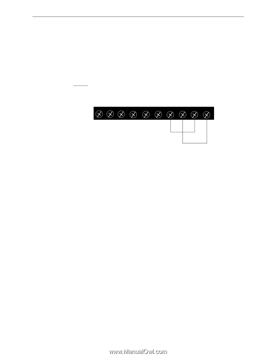
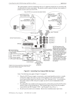
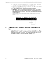
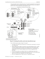
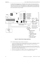
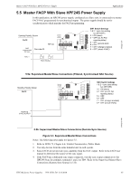
Applications Controlling Three NACs and One Door Holder With One Input 4. An End-of-Line Resistor must be installed between TB4, Terminals 5 & 6 for control module wiring supervision (the ELR value is dependent on the module employed). 5. Supervise the power wiring between the HPF24S auxiliary 24 VDC output on TB4, Terminals 9 & 10 with an EOL relay (P/N: A77-716B) 6. For a list of compatible devices, refer to the Device Compatibility Document. 7. IMPORTANT! When the power supply is programmed for both Selective Silence and Slave Mode, TB4 Terminal 7 (IN+) must be jumpered to Terminal 9 (AUX+) and Terminal 8 (IN-) must be jumpered to Terminal 10 (AUX-). The FACP will control the Selective Silence feature with this configuration. If the terminals are not jumpered as indicated, the horn portion of the horn/strobes will be silenced at all times. SYNC SYNC IN+ 1 2 3 TB4 IN- OUT+ OUT- IN2+ IN2- AUX+ AUX- 4 OU5T+ 6 7 8 9 10 5.2 Controlling Three NACs and One Door Holder With One Input In this application, the power supply has been set as a master with synchronized outputs. All four HPF24S output circuits, three NACs and one door holder, can be controlled from one input such as an addressable control module as illustrated in Figure 5.2. The control module can be powered from the HPF24S auxiliary 24 VDC power output (TB4, Terminals 9 & 10). 30 HPF24S Series Power Supplies - P/N 52751:D3 5/11/2010
-
 1
1 -
2
-
3
-
4
-
5
-
6
-
7
-
8
-
9
-
10
-
11
-
12
-
13
-
14
-
15
-
16
-
17
-
18
-
19
-
20
-
21
-
22
-
23
-
24
-
 25
25 -
 26
26 -
 27
27 -
 28
28 -
 29
29 -
 30
30 -
 31
31 -
 32
32 -
 33
33 -
 34
34 -
 35
35 -
36
-
37
-
38
-
39
-
40
-
41
-
42
-
43
-
44
-
45
-
46
-
47
-
48
-
49
-
50
-
51
-
52
 |
 |