Honeywell HPF24S8 Installation Instructions - Page 22
Programmable Features Description
 |
View all Honeywell HPF24S8 manuals
Add to My Manuals
Save this manual to your list of manuals |
Page 22 highlights
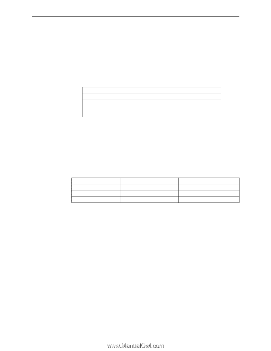
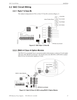
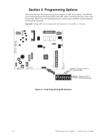
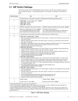
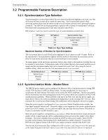
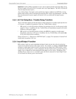
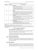
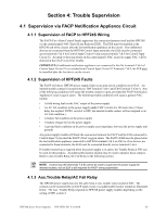
Programming Options 3.2 Programmable Features Description Programmable Features Description 3.2.1 Synchronization Type Selection Synchronization is a feature that controls the activation of notification appliances in such a way that all devices will turn on and off at exactly the same time. This is particularly critical when activating strobes which must be synchronized to avoid random activation and a potential hazard or confusion. The HPF24S can be programmed to operate with a variety of manufacturer's devices. Note that strobe synchronization works only with non-coded NACs. DIP switches 1 and 2 are used to select the type of synchronization as listed below: DIP Switch 1 OFF OFF ON ON DIP Switch 2 OFF ON OFF ON Synchronization Type no synchronization (steady 24V) System Sensor Gentex Wheelock Table 3.2 Sync Type Settings Maximum Number of Strobes for Synchronization The total current draw for each Notification Appliance Circuit cannot exceed 3.0 amps. Refer to the manufacturer's documentation supplied with the strobes to determine the maximum current draw for each strobe and ensure that the circuit maximum is not exceeded. To ensure proper strobe and circuit operation, there is also a limit to the number of strobes that can be attached to each circuit. Following is a table of the strobes that have been tested with the power supply and the maximum number that can be connected to each NAC when using the lowest candela setting. Make sure that the NAC maximum current is not exceeded: Strobe Manufacturer System Sensor Wheelock Gentex HPF24S6 (max. strobes) 51 30 39 HPF24S8 (max. strobes) 51 40 39 3.2.2 Synchronization Mode - Master/Slave The HPF24S power supply can be configured for Master or Slave Synchronization by setting DIP switch 3 ON for Slave or OFF for Master mode. In some installations, it is necessary to synchronize the flash timing of all strobes in the system for ADA compliance. Strobes accomplish this by monitoring very short timing pulses on the NAC power which are created by an FACP with synchronization capability. When installed at the end of an NAC wire run, this power supply can track (that is follow) the strobe synchronization timing pulses on the existing NAC wire run. This maintains the overall system flash timing of the additional strobes attached to this power supply. When this power supply is configured as a sync generator (Master Synchronization mode), the Sync Input terminals are not used. The power supply is the originator of the strobe synchronization pulses on its NAC outputs. In sync generator mode, the sync type (System Sensor, Wheelock, or Gentex) is selectable via DIP switches 1 and 2. When this power supply is configured as a sync follower (Slave Synchronization mode), the power supply's NAC outputs track the strobe synchronization pulses present at the supply's Sync Input terminals. The pulses originate from an upstream FACP or other power supply. Some FACPs provide synchronization timing pulses from a dedicated sync output connector. Connect the HPF24S sync input terminals to the FACP sync output connector instead of the FACP NAC. Note that the Synchronization Type configured by DIP switches 1 and 2 must be set to the same type as the signal being fed to the Sync Input circuit in the event that Selective Silence is employed. 22 HPF24S Series Power Supplies - P/N 52751:D3 5/11/2010
-
 1
1 -
2
-
3
-
4
-
5
-
6
-
7
-
8
-
9
-
10
-
11
-
12
-
13
-
14
-
15
-
16
-
 17
17 -
 18
18 -
 19
19 -
 20
20 -
 21
21 -
 22
22 -
 23
23 -
 24
24 -
 25
25 -
 26
26 -
 27
27 -
28
-
29
-
30
-
31
-
32
-
33
-
34
-
35
-
36
-
37
-
38
-
39
-
40
-
41
-
42
-
43
-
44
-
45
-
46
-
47
-
48
-
49
-
50
-
51
-
52
 |
 |