Honeywell HPF24S8 Installation Instructions - Page 25
Trouble Supervision
 |
View all Honeywell HPF24S8 manuals
Add to My Manuals
Save this manual to your list of manuals |
Page 25 highlights
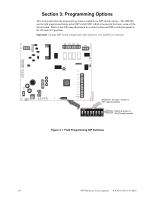
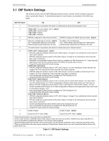
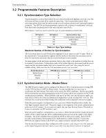
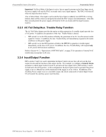
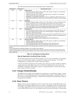
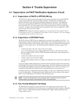
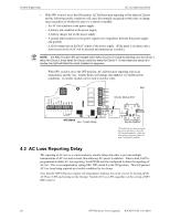
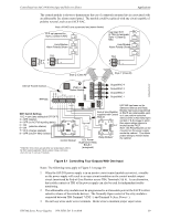
Section 4: Trouble Supervision 4.1 Supervision via FACP Notification Appliance Circuit 4.1.1 Supervision of FACP to HPF24S Wiring The FACP (Fire Alarm Control Panel) supervises the connection between itself and the HPF24S via the control panels NAC End-of-Line Resistor (ELR). The ELR must be installed at the HPF24S end of the circuit, after the last notification appliance on the circuit. If no additional devices are connected from the HPF24S Control Input terminals, the ELR must be connected across terminals 5 & 6 for Control Input Circuit #1 and across terminals 7 & 8 for Control Input Circuit #2. An open or short anywhere on the control panel's NAC or power supply NAC will be detected at the FACP as an NAC trouble. IMPORTANT: If additional notification appliances are connected to the Out terminals 5 & 6 of Control Input Circuit #1 or extended from Control Input Circuit #2 Terminals 7 & 8, the ELR must be installed after the last device on the circuit. 4.1.2 Supervision of HPF24S Faults The FACP will detect HPF24S power supply faults as an open circuit condition on its NAC. An internal trouble contact is located between TB4 Terminal 3 (In+) and TB4 Terminal 5 (Out+). Any of the following conditions will cause the trouble contact to open, provided the FACP Notification Appliance Circuit is not in alarm. The following trouble conditions will cause a general NAC trouble: • A field wiring fault on the NAC output of the power supply • An AC fail condition at the power supply (only if SW1 switch 4 is ON and a two (2) hour delay has expired. If SW1 switch 4 is OFF, the internal trouble contact will not respond to an AC Fail condition.) • A battery fail condition at the power supply • A battery charger fail on the power supply • A ground fault condition on the power supply (zero impedance between the power supply and ground) Any power supply trouble will break the connection between the FACP and the ELR connected to Control Input #1 provided the FACP's NAC is not in alarm. The FACP's ELR must be placed after the last notification appliance connected to HPF24S terminals 5 & 6 on TB4 or, if no devices are connected to these terminals, the ELR must be connected directly across terminals 5 & 6. If trouble monitoring is required when the power supply is in alarm, the Trouble Relay at TB5 can be used for this purpose. An addressable monitor module may be used to monitor these contacts. Refer to Aux.Trouble Relay/AC Fail Relay in the following section. NOTE: Control Input #2 (terminals 7 & 8) cannot be used to supervise the power supply for internal troubles, but an ELR is still required for FACP wiring supervision. 4.1.3 Aux.Trouble Relay/AC Fail Relay The HPF24S power supply has one fail-safe Form-C aux. trouble relay located at TB5. The contacts can be monitored by an FACP input circuit or an addressable monitor module as illustrated below. The Aux. Trouble Relay responds to HPF24S power supply troubles depending on the setting of SW1 switch 4. HPF24S Series Power Supplies - P/N 52751:D3 5/11/2010 25
-
 1
1 -
2
-
3
-
4
-
5
-
6
-
7
-
8
-
9
-
10
-
11
-
12
-
13
-
14
-
15
-
16
-
17
-
18
-
19
-
 20
20 -
 21
21 -
 22
22 -
 23
23 -
 24
24 -
 25
25 -
 26
26 -
 27
27 -
 28
28 -
 29
29 -
 30
30 -
31
-
32
-
33
-
34
-
35
-
36
-
37
-
38
-
39
-
40
-
41
-
42
-
43
-
44
-
45
-
46
-
47
-
48
-
49
-
50
-
51
-
52
 |
 |