Honeywell HPF24S8 Installation Instructions - Page 21
DIP Switch Settings
 |
View all Honeywell HPF24S8 manuals
Add to My Manuals
Save this manual to your list of manuals |
Page 21 highlights
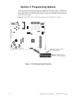
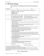
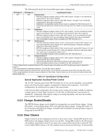
DIP Switch Settings Programming Options 3.1 DIP Switch Settings The following table lists the HPF24Sprogrammable features and the switch settings required to select a particular feature. A detailed description of each feature is presented in the following pages. SW1 DIP Switch ON OFF 1 This switch works in conjunction with switch 2 to determine the Strobe Synchronization Type1. 2 1 OFF, 2 OFF = no sync (steady +24V) - default 1 OFF, 2 ON = System Sensor 1 ON, 2 OFF = Gentex 1 ON, 2 ON = Wheelock 3 HPF24S configured for Slave Synchronization HPF24S configured for Master Synchronization - default 4 Delay AC Fail Reporting for 2 Hours - default No Delay in AC Fail Reporting Aux. Trouble Relay responds to all troubles. Aux. Trouble Relay responds only to AC Fail/brownout. Internal trouble contact responds to AC loss Internal trouble contact will not respond to AC loss. 5 This switch works in conjunction with switch 6 to determine Input to Output functions 6 5 OFF, 6 OFF = General Alarm - default • HPF24S configured as Master (switch 3 OFF), NAC Outputs 1 through 42 are controlled by Control Input #1; Sync Input is ignored. • HPF24S configured as Slave (switch 3 ON), NAC Outputs 1 through 42 are controlled by Control Input #1; Sync Input is monitored3. • Resettable or nonresettable Auxiliary Power Output is available from TB4 Terminals 9 & 10. Control Input #2 determines if reset will occur (must go from On to Off for a 6 second reset to occur). • Output #4 function follows DIP switch 8 setting. 5 OFF, 6 ON = Split Alarm • HPF24S configured as Master (switch 3 OFF), NAC Outputs 1 & 2 are controlled by Control Input #1 and Outputs 3 & 42 are controlled by Control Input #2; Sync Input is ignored. • HPF24S configured as Slave5 (switch 3 ON), NAC Outputs 1 & 2 are controlled by Control Input #1 and Outputs 3 & 42 are controlled by Control Input #2; Sync Input is monitored3. • Only nonresettable Auxiliary Power is available from TB4 Terminals 9 & 10. • Output #4 function follows DIP switch 8 setting. 5 ON, 6 OFF = Split Temporal • HPF24S configured as Master (switch 3 OFF), Control Input #1 controls NAC Outputs 1 & 2 and Control Input #2 controls Outputs 3 & 42 which will generate a Temporal code signal without sync; Sync Input is ignored. HPF24S configured as Slave (switch 3 ON), Control Input #1 controls NAC Outputs 1 & 2 and Control Input #2 controls Outputs 3 & 42 which will generate a Temporal code signal without sync; Sync Input is monitored for Outputs 1 & 23. • Only nonresettable Auxiliary Power is available from TB4 Terminals 9 & 10. • Output #4 function follows DIP switch 8 setting. 5 ON, 6 ON = Selective Silence • HPF24S configured as Master (switch 3 OFF), NAC Outputs 1 through 42 are controlled by Control Input #1; Sync Input is ignored. • HPF24S configured as Slave (switch 3 ON), NAC Outputs 1 through 42 are controlled by Control Input #1; Sync Input is monitored3. • Control Input #2 determines when Selective Silence for all outputs will occur4 • Only nonresettable Auxiliary Power is available from TB4 Terminals 9 & 10. • Output #4 function follows DIP switch 8 setting. 7 Disable Charger Enable Charger - default 8 Output Circuit #4 = Door Holder Output Circuit #4 = NAC - default 1 Strobe Synchronization only works with non-coded NACs. 2 If Door Closer function is selected (switch 8 ON), Output 4 does not function as an NAC, therefore sync input is ignored for it. 3 If no synchronization is selected by switches 1 & 2, the Sync Input is ignored. 4 Selective Silence allows the silencing of the sounder portion of a horn/strobe combination device without turning off the strobe. 5 When using Split Alarm with power supply configured in Slave Mode, System Sensor can not be used (Use System Sensor with Master Mode only). Table 3.1 DIP Switch Settings HPF24S Series Power Supplies - P/N 52751:D3 5/11/2010 21
-
 1
1 -
2
-
3
-
4
-
5
-
6
-
7
-
8
-
9
-
10
-
11
-
12
-
13
-
14
-
15
-
 16
16 -
 17
17 -
 18
18 -
 19
19 -
 20
20 -
 21
21 -
 22
22 -
 23
23 -
 24
24 -
 25
25 -
 26
26 -
27
-
28
-
29
-
30
-
31
-
32
-
33
-
34
-
35
-
36
-
37
-
38
-
39
-
40
-
41
-
42
-
43
-
44
-
45
-
46
-
47
-
48
-
49
-
50
-
51
-
52
 |
 |
