Honeywell HPF24S8 Installation Instructions - Page 42
Appendix A: Wire Requirements
 |
View all Honeywell HPF24S8 manuals
Add to My Manuals
Save this manual to your list of manuals |
Page 42 highlights
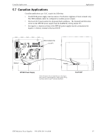
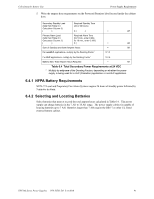
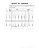
Appendix A: Wire Requirements Connecting external system accessories to the main circuits must be carefully considered to ensure proper operation. It is important to use the correct type of wire, gauge and run length for each circuit. The following table lists NAC wiring requirements for the HPF24S6 and HPF24S8 Field Charger Power Supply. NAC Load (Amps) 0.25 0.5 0.75 1.0 1.25 1.5 1.75 2.0 2.25 2.5 2.75 3.0 Max. allowable total loop resistance (ohms) CLASS-B Max. allowable wire pair length (feet) AWG 12 AWG 14 AWG 16 AWG 18 solid solid solid solid CLASS-A Max. allowable wire pair length (feet) AWG 12 AWG 14 AWG 16 AWG 18 solid solid solid solid 12.80 3316 2085 1309 824 1658 1042 654 412 6.40 1658 1042 654 412 829 521 327 206 4.27 1105 695 436 275 553 347 218 137 3.20 829 521 327 206 415 261 164 103 2.56 663 417 262 165 332 208 131 82 2.13 553 347 218 137 276 174 109 69 1.83 474 298 187 118 237 149 93 59 1.60 415 261 164 103 207 130 82 51 1.42 368 232 145 92 184 116 73 46 1.28 332 208 131 82 166 104 65 41 1.16 301 190 119 75 151 95 59 37 1.07 276 174 109 69 138 87 55 34 Table A.1 NAC Wiring Requirements for Power Supply Calculations are based on Direct-Current Resistance data for uncoated copper wire, per National Electrical Code (2005 Edition) Table 8, Conductor Properties. 42 HPF24S Series Power Supplies - P/N 52751:D3 5/11/2010
-
 1
1 -
2
-
3
-
4
-
5
-
6
-
7
-
8
-
9
-
10
-
11
-
12
-
13
-
14
-
15
-
16
-
17
-
18
-
19
-
20
-
21
-
22
-
23
-
24
-
25
-
26
-
27
-
28
-
29
-
30
-
31
-
32
-
33
-
34
-
35
-
36
-
 37
37 -
 38
38 -
 39
39 -
 40
40 -
 41
41 -
 42
42 -
 43
43 -
 44
44 -
 45
45 -
 46
46 -
 47
47 -
48
-
49
-
50
-
51
-
52
 |
 |