Honeywell HPF24S8 Installation Instructions - Page 15
Installation
 |
View all Honeywell HPF24S8 manuals
Add to My Manuals
Save this manual to your list of manuals |
Page 15 highlights
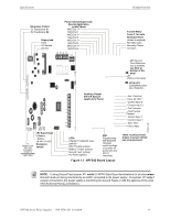
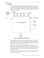
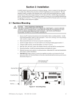
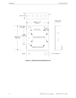
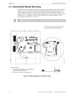
Section 2: Installation Carefully unpack the system and check for shipping damage. Select a location for the cabinet that is in a clean, dry, vibration-free area where extreme temperatures are not encountered. The area should be readily accessible with sufficient room to easily install and maintain the power supply. Locate the top of the cabinet approximately five feet above the floor with the hinge mounting on the left. Determine the number of conductors required for the devices to be installed and determine the appropriate knockouts. All wiring must be in accordance with the National and/or Local codes for fire alarm systems and power supplies. 2.1 Backbox Mounting ! CAUTION: STATIC SENSITIVE COMPONENTS THE CIRCUIT BOARD CONTAINS STATIC-SENSITIVE COMPONENTS. ALWAYS GROUND YOURSELF WITH A PROPER WRIST STRAP BEFORE HANDLING ANY BOARDS SO THAT STATIC CHARGES ARE REMOVED FROM THE BODY. USE STATIC SUPPRESSIVE PACKAGING TO PROTECT ELECTRONIC ASSEMBLIES. 1. Remove the PC board and transformers from the backbox before installing backbox. Set the board and transformers aside in a safe, clean place. Avoid static discharge which may damage static sensitive components on the board. 2. Mark and predrill holes for the top two keyhole mounting bolts. 3. Install two upper fasteners in the wall with the screw heads protruding approximately ¼". 4. Using the upper keyholes, mount the backbox over the two screws. 5. Mark the lower two holes, remove the backbox from the wall and drill the mounting holes. 6. Mount the backbox, install the remaining fasteners and tighten all screws. 7. When the location is dry and free of construction dust, reinstall the PC board and transformers and continue with the installation. 8. IMPORTANT! Make certain to connect the supplied grounding strap between the Earth terminal on TB1 (AC Terminal Block) of the main circuit board and the chassis ground stud as illustrated in Figure 2.1: Earth Terminal on TB1 (AC Terminal Block) Mounting Plate 24fsgrnd.wmf Grounding Strap Ground Stud Backbox Figure 2.1 Grounding Strap HPF24S Series Power Supplies - P/N 52751:D3 5/11/2010 15
-
 1
1 -
2
-
3
-
4
-
5
-
6
-
7
-
8
-
9
-
 10
10 -
 11
11 -
 12
12 -
 13
13 -
 14
14 -
 15
15 -
 16
16 -
 17
17 -
 18
18 -
 19
19 -
 20
20 -
21
-
22
-
23
-
24
-
25
-
26
-
27
-
28
-
29
-
30
-
31
-
32
-
33
-
34
-
35
-
36
-
37
-
38
-
39
-
40
-
41
-
42
-
43
-
44
-
45
-
46
-
47
-
48
-
49
-
50
-
51
-
52
 |
 |
