Honeywell HPF24S8 Installation Instructions - Page 40
Calculating the Battery Size
 |
View all Honeywell HPF24S8 manuals
Add to My Manuals
Save this manual to your list of manuals |
Page 40 highlights
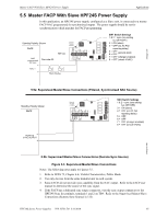
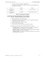
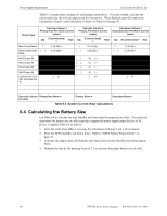
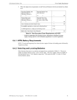
Power Supply Requirements Calculating the Battery Size Table 6.3 contains three columns for calculating current draws. For each column, calculate the current and enter the total (in amperes) in the bottom row. When finished, copy the totals from Calculation Column 2 and Calculation Column 3 to Table 6.4 on page 41. Device Type Calculate Column 1 Primary, Non-Fire Alarm Current (amps) Qty X (current draw) = Total Main Circuit Board 1 X [ 0.091] = Power Supervision [ ] Relay X [ 0.025] = NAC/Output #1 NAC/Output #2 NAC/Output #3 NAC/Output #4 Current Draw from TB4 Terminals 9 & 10 [ ]= Calculate Column 2 Primary, Fire Alarm Current (amps) Qty X (current draw) = Total 1 X [ 0.145] = [ ] X [0.025 ] = X[ ]= X[ ]= X[ ]= X[ ]= [ ]= Calculation Column 3 Secondary, Non-Fire Alarm Current (amps) Qty X (current draw) = Total 1 [ ] X [ 0.065] = X [ 0.025] = [ ]= Sum each column Primary Non-Alarm = for totals Primary Alarm = Secondary Alarm = Table 6.3 System Current Draw Calculations 6.4 Calculating the Battery Size Use Table 6.4 to calculate the total Standby and Alarm load in ampere hours (AH). This total load determines the battery size (in AH) required to support the power supply under the loss of AC power. Complete Table 6.4 as follows: 1. Enter the totals from Table 6.3 on page 40, Calculation Columns 2 and 3 where shown. 2. Enter the NFPA Standby and Alarm times. Refer to "NFPA Battery Requirements" on page 41. 3. Calculate the ampere hours for Standby and Alarm, then sum the Standby and Alarm ampere hours. 4. Multiply the sum by the derating factor of 1.2 to calculate the proper battery size (in AH). 40 HPF24S Series Power Supplies - P/N 52751:D3 5/11/2010
-
 1
1 -
2
-
3
-
4
-
5
-
6
-
7
-
8
-
9
-
10
-
11
-
12
-
13
-
14
-
15
-
16
-
17
-
18
-
19
-
20
-
21
-
22
-
23
-
24
-
25
-
26
-
27
-
28
-
29
-
30
-
31
-
32
-
33
-
34
-
 35
35 -
 36
36 -
 37
37 -
 38
38 -
 39
39 -
 40
40 -
 41
41 -
 42
42 -
 43
43 -
 44
44 -
 45
45 -
46
-
47
-
48
-
49
-
50
-
51
-
52
 |
 |
