Honeywell HPF24S8 Installation Instructions - Page 37
Canadian Applications
 |
View all Honeywell HPF24S8 manuals
Add to My Manuals
Save this manual to your list of manuals |
Page 37 highlights
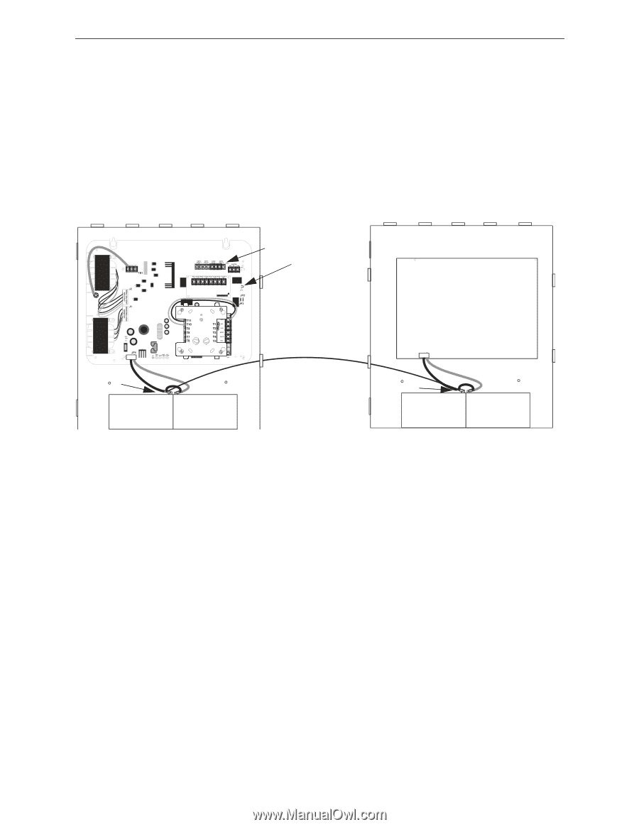
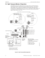
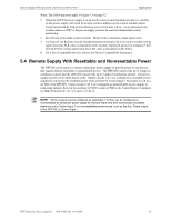
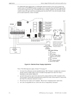
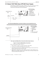
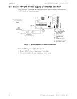
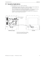
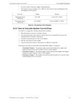
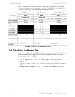
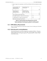
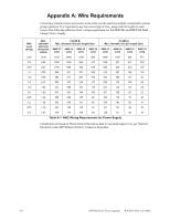
Canadian Applications Applications 5.7 Canadian Applications Canadian applications, per ULC, require the following: • The HPF24S power supply must be used as a Notification Appliance Circuit extender only. The TB2 terminals cannot be configured as auxiliary power outputs. • The host FACP must monitor for all ground fault conditions. The Ground Fault Detection circuit on the HPF24S power supply must be disabled by cutting jumper JP1. • the negative (-) battery terminal of the HPF24S power supply must be connected to the negative (-) battery terminal of the host FACP. NAC Outputs only Cut JP1 24fsCanadiantpH.wmf Battery - Battery - HPF24S Power Supply *If the SLC device does not match the one in this figure, refer to the SLC manual appendix, which contains wiring conversion charts for type V and type H modules. Host FACP HPF24S Series Power Supplies - P/N 52751:D3 5/11/2010 37
-
 1
1 -
2
-
3
-
4
-
5
-
6
-
7
-
8
-
9
-
10
-
11
-
12
-
13
-
14
-
15
-
16
-
17
-
18
-
19
-
20
-
21
-
22
-
23
-
24
-
25
-
26
-
27
-
28
-
29
-
30
-
31
-
 32
32 -
 33
33 -
 34
34 -
 35
35 -
 36
36 -
 37
37 -
 38
38 -
 39
39 -
 40
40 -
 41
41 -
 42
42 -
43
-
44
-
45
-
46
-
47
-
48
-
49
-
50
-
51
-
52
 |
 |