Honeywell HPF24S8 Installation Instructions - Page 18
Addressable Module Mounting
 |
View all Honeywell HPF24S8 manuals
Add to My Manuals
Save this manual to your list of manuals |
Page 18 highlights
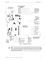
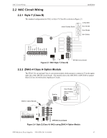
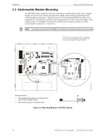
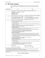
Installation Addressable Module Mounting 2.3 Addressable Module Mounting The HPF24S has been designed to allow the mounting of an addressable control, relay or monitor module on the main circuit board inside the power supply cabinet with the module status LED visible through the closed door. This allows power to be fed from the HPF24S Auxiliary Power output directly to the module, if needed, without running the power wires outside the cabinet. As an example, Figure 2.5 illustrates wiring from the Auxiliary power output terminals to a FCM-1 control module's terminals 11 (-) and 10 (+). NOTE: The module mounting kit (P/N 90286) is pre-installed on the power supply main circuit board. *If the SLC device does not match the one in this figure, refer to the SLC manual appendix, which contains wiring conversion charts for type V and type H modules. 24fsmodltpH.wmf standoff standoff standoff standoff Module Installation 1. Place addressable module over (4) standoffs and secure with (4) supplied screws. 2. Wire module as shown in illustration above. Figure 2.5 Mounting Module In HPF24S Cabinet 18 HPF24S Series Power Supplies - P/N 52751:D3 5/11/2010
-
 1
1 -
2
-
3
-
4
-
5
-
6
-
7
-
8
-
9
-
10
-
11
-
12
-
 13
13 -
 14
14 -
 15
15 -
 16
16 -
 17
17 -
 18
18 -
 19
19 -
 20
20 -
 21
21 -
 22
22 -
 23
23 -
24
-
25
-
26
-
27
-
28
-
29
-
30
-
31
-
32
-
33
-
34
-
35
-
36
-
37
-
38
-
39
-
40
-
41
-
42
-
43
-
44
-
45
-
46
-
47
-
48
-
49
-
50
-
51
-
52
 |
 |
