Honeywell HPF24S8 Installation Instructions - Page 31
Controlling Three NACs and One Door Holder With One Input
 |
View all Honeywell HPF24S8 manuals
Add to My Manuals
Save this manual to your list of manuals |
Page 31 highlights
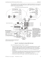
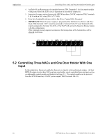
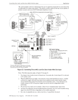
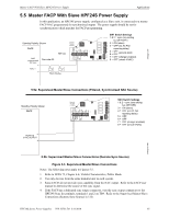
Controlling Three NACs and One Door Holder With One Input Applications The control module is shown to demonstrate the use of a remotely mounted device associated with an addressable fire alarm control panel. The module could be replaced with any circuit capable of polarity reversal, such as an FACP Notification Appliance Circuit. Note: All NACs are supervised and power-limited ELR not required for Style Z (Class A) NAC Door Holder Horn/Strobes Alarm Polarity Shown Use listed ELR (4.7K) to terminate Style Y (Class B) NAC Door Holder Horn/Strobes Alarm Polarity Shown Internal Trouble Contact HPF24S Style Z (Class A) ZNAC-4 Option Module SLC End-of-Line Resistor supplied with Control Module Style Y (Class B) Door Holder Circuit 4 Output/NAC 3 Output/NAC 2 Output/NAC 1 SW1 Switch Settings 1 & 2 = sync (any setting but OFF/OFF) 3 = OFF (master) 4 = OFF (no AC Fail reporting delay) 5 = OFF (general alarm) 6 = OFF 7 = OFF (charger enabled) 8 = ON (circuit 4 door holder) 24fsapp6tpH.wmf Control Module* *If the SLC device does not match the one in this figure, refer to the SLC manual appendix, which contains wiring conversion charts for type V and type H modules. Figure 5.2 Controlling Three NACs and One Door Holder With One Input Notes: The following notes apply to Figure 5.2 on page 31. 1. The Output 4 door holder circuit will deactivate 10 seconds after Control Input #1 is activated or AC power is lost. 2. When the HPF24S power supply is in an inactive state (control module not active), a trouble on the power supply will result in an open circuit condition on the control module output circuit (monitored by End-of-Line Resistor across Terminals 5 & 6). As an alternative, the trouble contacts at TB5 of the power supply can also be used for independent trouble monitoring. 3. Do not loop wires under screw terminals. Break wires to maintain proper supervision. 4. An End-of-Line Resistor must be installed between terminals 5 & 6 for control module wiring supervision (the ELR value is dependent on the module employed). 5. For a list of compatible devices, refer to the Device Compatibility Document. HPF24S Series Power Supplies - P/N 52751:D3 5/11/2010 31
-
 1
1 -
2
-
3
-
4
-
5
-
6
-
7
-
8
-
9
-
10
-
11
-
12
-
13
-
14
-
15
-
16
-
17
-
18
-
19
-
20
-
21
-
22
-
23
-
24
-
25
-
 26
26 -
 27
27 -
 28
28 -
 29
29 -
 30
30 -
 31
31 -
 32
32 -
 33
33 -
 34
34 -
 35
35 -
 36
36 -
37
-
38
-
39
-
40
-
41
-
42
-
43
-
44
-
45
-
46
-
47
-
48
-
49
-
50
-
51
-
52
 |
 |
