Honeywell HPF24S8 Installation Instructions - Page 24
Charger Enable/Disable, Door Closers
 |
View all Honeywell HPF24S8 manuals
Add to My Manuals
Save this manual to your list of manuals |
Page 24 highlights
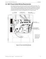
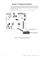
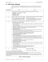
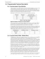
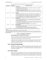
Programming Options Programmable Features Description The following table details the four possible input/output configurations: DIP Switch 5 DIP Switch 6 Input/Output Function OFF OFF General Alarm • HPF24S configured as Master (switch 3 OFF), NAC Outputs 1 through 41 are controlled by Control Input #1; Sync Input is ignored. • HPF24S configured as Slave (switch 3 ON), NAC Outputs 1 through 42 are controlled by Control Input #1; Sync Input is monitored2. • Resettable or nonresettable Auxiliary Power Output is available from TB4 Terminals 9 & 10. Control Input #2 determines if reset will occur (must go from On to Off for a 6 second reset to occur). OFF ON Split Alarm • HPF24S configured as Master (switch 3 OFF), NAC Outputs 1 & 2 are controlled by Control Input #1 and Outputs 3 & 41 are controlled by Control Input #2; Sync Input is ignored. • HPF24S configured as Slave4 (switch 3 ON), NAC Outputs 1 & 2 are controlled by Control Input #1 and Outputs 3 & 41 are controlled by Control Input #2; Sync Input is monitored2. • Only nonresettable Auxiliary Power is available from TB4 Terminals 9 & 10 ON OFF Split Temporal • HPF24S configured as Master (switch 3 OFF), Control Input #1 controls NAC Outputs 1 & 2 and Control Input #2 controls Outputs 3 & 41 which will generate a Temporal code signal without sync; Sync Input is ignored. • HPF24S configured as Slave (switch 3 ON), Control Input #1 controls NAC Outputs 1 & 2 and Control Input #2 controls Outputs 3 & 41 which will generate a Temporal code signal without sync; Sync Input is monitored for Outputs 1 & 22. • Only nonresettable Auxiliary Power is available from TB4 Terminals 9 & 10 ON ON Selective Silence3 • HPF24S configured as Master (switch 3 OFF), NAC Outputs 1 through 41 are controlled by Control Input #1; Sync Input is ignored. • Control Input #2 determines when Selective Silence for all outputs will occur. • Only nonresettable Auxiliary Power is available from TB4 Terminals 9 & 10 1 If Door Closer function is selected (switch 8 ON), Output 4 does not function as an NAC, therefore sync input is ignored for Output 4. 2 If no synchronization is selected by switches 1 & 2, the Sync Input is ignored. 3 Selective Silence allows the silencing of the sounder portion of a horn/strobe combination device without turning off the strobe. 4 When using Split Alarm with power supply configured in Slave Mode, System Sensor can not be used (Use System Sensor with Master Mode only) Table 3.3 Input/Output Configurations Special Application Auxiliary Power Control The 24 VDC Auxiliary power from TB4 Terminals 9(+) & 10(-) can be resettable or nonresettable power only when the power supply is configured for General Alarm operation. For all other configurations, the auxiliary power output is only nonresettable. In the General Alarm configuration, the Auxiliary power output can be made resettable by applying a steady signal to Control Input 2 (positive 12 to 24 VDC on TB4 Terminal 7 and common on Terminal 8). Temporarily removing the voltage or reversing the polarity will cause the Auxiliary power output to reset for 6 seconds. 3.2.5 Charger Enable/Disable The HPF24S battery charger can be disabled to accommodate an external battery charger. Setting DIP switch 7 to the default setting of OFF will enable the battery charger. Setting DIP switch 7 to the ON position will disable the charger. It should only be disabled if an external battery charger is being used for the HPF24S. 3.2.6 Door Closers Output Circuit #4 can be configured as an NAC or door closer circuit. Setting DIP switch 8 to the OFF position will configure Output Circuit #4 as an NAC. Setting DIP switch 8 to the ON position will configure only Output Circuit #4 as a door closer circuit which will provide a steady 24 VDC to door holders until an alarm or AC fail condition removes the power following a 10 second delay. 24 HPF24S Series Power Supplies - P/N 52751:D3 5/11/2010
-
 1
1 -
2
-
3
-
4
-
5
-
6
-
7
-
8
-
9
-
10
-
11
-
12
-
13
-
14
-
15
-
16
-
17
-
18
-
 19
19 -
 20
20 -
 21
21 -
 22
22 -
 23
23 -
 24
24 -
 25
25 -
 26
26 -
 27
27 -
 28
28 -
 29
29 -
30
-
31
-
32
-
33
-
34
-
35
-
36
-
37
-
38
-
39
-
40
-
41
-
42
-
43
-
44
-
45
-
46
-
47
-
48
-
49
-
50
-
51
-
52
 |
 |
