Honeywell HPF24S8 Installation Instructions - Page 17
NAC Circuit Wiring
 |
View all Honeywell HPF24S8 manuals
Add to My Manuals
Save this manual to your list of manuals |
Page 17 highlights
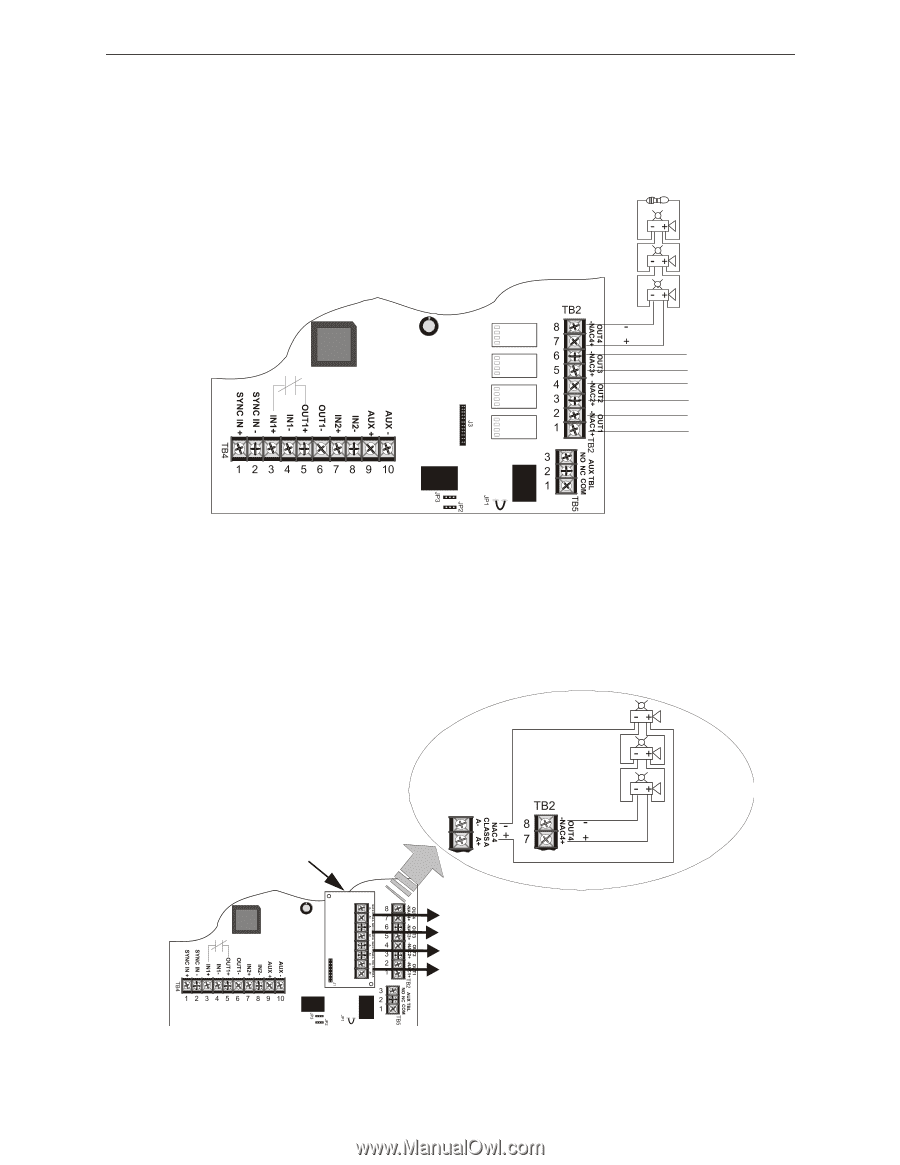
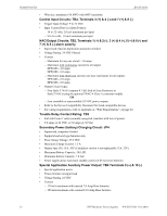
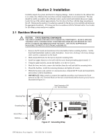
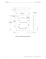
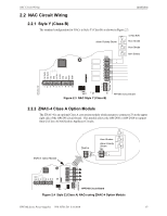
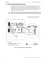
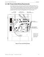
NAC Circuit Wiring 2.2 NAC Circuit Wiring Installation 2.2.1 Style Y (Class B) The standard configuration for NACs is Style Y (Class B) as shown in Figure 2.3. Alarm Polarity Shown 4.7K ELR Horn Strobe Horn Strobe Horn Strobe 24fsclsb.wmf Figure 2.3 NAC Style Y (Class B) HPF24S Circuit Board 2.2.2 ZNAC-4 Class A Option Module The ZNAC-4 is an optional Class A conversion module which mounts to connector J3 on the upper right side of the HPF24S circuit board. This module allows the HPF24S6 or HPF24S8 to support Style Z (Class A) Notification Appliance Circuits. ZNAC-4 Option Module ZNAC-4 Horn Strobes Alarm Polarity Shown 24fsclsa.cdr J3 HPF24S Circuit Board Figure 2.4 Style Z (Class A) NACs using ZNAC-4 Option Module HPF24S Series Power Supplies - P/N 52751:D3 5/11/2010 17
-
 1
1 -
2
-
3
-
4
-
5
-
6
-
7
-
8
-
9
-
10
-
11
-
 12
12 -
 13
13 -
 14
14 -
 15
15 -
 16
16 -
 17
17 -
 18
18 -
 19
19 -
 20
20 -
 21
21 -
 22
22 -
23
-
24
-
25
-
26
-
27
-
28
-
29
-
30
-
31
-
32
-
33
-
34
-
35
-
36
-
37
-
38
-
39
-
40
-
41
-
42
-
43
-
44
-
45
-
46
-
47
-
48
-
49
-
50
-
51
-
52
 |
 |