IBM 7945E2U User Manual - Page 51
SAS riser-card connectors and LEDs, following illustration.
 |
View all IBM 7945E2U manuals
Add to My Manuals
Save this manual to your list of manuals |
Page 51 highlights
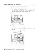
SAS riser-card connectors and LEDs The following illustrations show the connectors and LEDs on the SAS riser-cards. Note: Error LEDs remain lit only while the server is connected to power. A 16-drive-capable model server contains the riser card that is shown in the following illustration. USB hypervisor connector PCI Express SAS controller connector SAS controller error LED SAS riser card A tape-enabled model server contains the riser card that is shown in the following illustration. USB hypervisor connector PCI Express SAS controller connector SATA tape signal Tape drive power USB tape signal SAS controller error LED SAS riser card (tape-enabled model server) Chapter 2. Installing optional devices 35
-
 1
1 -
2
-
3
-
4
-
5
-
6
-
7
-
8
-
9
-
10
-
11
-
12
-
13
-
14
-
15
-
16
-
17
-
18
-
19
-
20
-
21
-
22
-
23
-
24
-
25
-
26
-
27
-
28
-
29
-
30
-
31
-
32
-
33
-
34
-
35
-
36
-
37
-
38
-
39
-
40
-
41
-
42
-
43
-
44
-
45
-
 46
46 -
 47
47 -
 48
48 -
 49
49 -
 50
50 -
 51
51 -
 52
52 -
 53
53 -
 54
54 -
 55
55 -
 56
56 -
57
-
58
-
59
-
60
-
61
-
62
-
63
-
64
-
65
-
66
-
67
-
68
-
69
-
70
-
71
-
72
-
73
-
74
-
75
-
76
-
77
-
78
-
79
-
80
-
81
-
82
-
83
-
84
-
85
-
86
-
87
-
88
-
89
-
90
-
91
-
92
-
93
-
94
-
95
-
96
-
97
-
98
-
99
-
100
-
101
-
102
-
103
-
104
-
105
-
106
-
107
-
108
-
109
-
110
-
111
-
112
-
113
-
114
-
115
-
116
-
117
-
118
-
119
-
120
-
121
-
122
-
123
-
124
-
125
-
126
-
127
-
128
-
129
-
130
-
131
-
132
-
133
-
134
-
135
-
136
-
137
-
138
-
139
-
140
-
141
-
142
-
143
-
144
-
145
-
146
-
147
-
148
-
149
-
150
-
151
-
152
-
153
-
154
-
155
-
156
-
157
-
158
-
159
-
160
-
161
-
162
-
163
-
164
-
165
-
166
-
167
-
168
-
169
-
170
-
171
-
172
-
173
-
174
-
175
-
176
-
177
-
178
-
179
-
180
-
181
-
182
-
183
-
184
-
185
-
186
-
187
-
188
-
189
-
190
-
191
-
192
-
193
-
194
 |
 |

SAS riser-card connectors and LEDs
The following illustrations show the connectors and LEDs on the SAS riser-cards.
Note:
Error LEDs remain lit only while the server is connected to power.
A 16-drive-capable model server contains the riser card that is shown in the
following illustration.
USB hypervisor
connector
PCI Express SAS
controller connector
SAS controller
error LED
SAS riser
card
A tape-enabled model server contains the riser card that is shown in the following
illustration.
USB hypervisor
connector
USB
tape
signal
PCI Express SAS
controller connector
SATA tape signal
Tape drive
power
SAS controller
error LED
SAS riser card
(tape-enabled model server)
Chapter 2. Installing optional devices
35