IBM 7945E2U User Manual - Page 71
seated in the PCI riser-card connector on the system board.
 |
View all IBM 7945E2U manuals
Add to My Manuals
Save this manual to your list of manuals |
Page 71 highlights
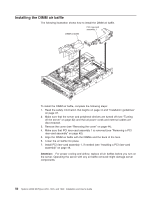
PCI riser connector 2 PCI riser-card assembly 2 PCI riser-card assembly 1 Alignment slots Alignment brackets PCI riser connector 1 v PCI riser-card connector 1: Carefully fit the two alignment slots on the side of the assembly onto the two alignment brackets in the side of the chassis; align the rear of the assembly with the guides on the rear of the server. v PCI riser-card connector 2: Carefully align the bottom edge (the contact edge) of the riser-card assembly with the PCI riser-card connector on the system board; align the rear of the assembly with the guides on the rear of the server. 10. Press down on the assembly. Make sure that the riser-card assembly is fully seated in the PCI riser-card connector on the system board. 11. Perform any configuration tasks that are required for the adapter. If you have other devices to install or remove, do so now. Otherwise, go to "Completing the installation" on page 139. Chapter 2. Installing optional devices 55
-
 1
1 -
2
-
3
-
4
-
5
-
6
-
7
-
8
-
9
-
10
-
11
-
12
-
13
-
14
-
15
-
16
-
17
-
18
-
19
-
20
-
21
-
22
-
23
-
24
-
25
-
26
-
27
-
28
-
29
-
30
-
31
-
32
-
33
-
34
-
35
-
36
-
37
-
38
-
39
-
40
-
41
-
42
-
43
-
44
-
45
-
46
-
47
-
48
-
49
-
50
-
51
-
52
-
53
-
54
-
55
-
56
-
57
-
58
-
59
-
60
-
61
-
62
-
63
-
64
-
65
-
 66
66 -
 67
67 -
 68
68 -
 69
69 -
 70
70 -
 71
71 -
 72
72 -
 73
73 -
 74
74 -
 75
75 -
 76
76 -
77
-
78
-
79
-
80
-
81
-
82
-
83
-
84
-
85
-
86
-
87
-
88
-
89
-
90
-
91
-
92
-
93
-
94
-
95
-
96
-
97
-
98
-
99
-
100
-
101
-
102
-
103
-
104
-
105
-
106
-
107
-
108
-
109
-
110
-
111
-
112
-
113
-
114
-
115
-
116
-
117
-
118
-
119
-
120
-
121
-
122
-
123
-
124
-
125
-
126
-
127
-
128
-
129
-
130
-
131
-
132
-
133
-
134
-
135
-
136
-
137
-
138
-
139
-
140
-
141
-
142
-
143
-
144
-
145
-
146
-
147
-
148
-
149
-
150
-
151
-
152
-
153
-
154
-
155
-
156
-
157
-
158
-
159
-
160
-
161
-
162
-
163
-
164
-
165
-
166
-
167
-
168
-
169
-
170
-
171
-
172
-
173
-
174
-
175
-
176
-
177
-
178
-
179
-
180
-
181
-
182
-
183
-
184
-
185
-
186
-
187
-
188
-
189
-
190
-
191
-
192
-
193
-
194
 |
 |
