IBM 7945E2U User Manual - Page 61
Removing a PCI riser-card assembly, Turn off the server and peripheral devices
 |
View all IBM 7945E2U manuals
Add to My Manuals
Save this manual to your list of manuals |
Page 61 highlights
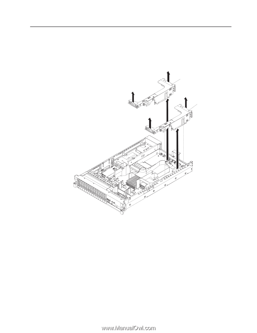
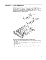
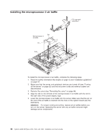
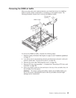
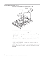
Removing a PCI riser-card assembly The server comes with one riser-card assembly (with option to add one more) that each contain two PCI Express x8 connectors. You can replace a PCI Express riser-card assembly with a riser-card assembly that contains one PCI Express Gen 2 x16 connector or that contains two PCI-X 64-bit 133 MHz connectors. See http://www.ibm.com/servers/eserver/serverproven/compat/us/ for a list of riser-card assemblies that you can use with the server. PCI riser-card assembly 2 PCI riser-card assembly 1 To remove the riser-card assembly, complete the following steps: 1. Read the safety information that begins on page vii and "Installation guidelines" on page 37. 2. Turn off the server and peripheral devices, and disconnect the power cord and all external cables. 3. Remove the cover (see "Removing the cover" on page 44). 4. Grasp the assembly at the front tab and rear edge and lift it to remove it from the server. Place the riser-card assembly on a flat, static-protective surface. Chapter 2. Installing optional devices 45
-
 1
1 -
2
-
3
-
4
-
5
-
6
-
7
-
8
-
9
-
10
-
11
-
12
-
13
-
14
-
15
-
16
-
17
-
18
-
19
-
20
-
21
-
22
-
23
-
24
-
25
-
26
-
27
-
28
-
29
-
30
-
31
-
32
-
33
-
34
-
35
-
36
-
37
-
38
-
39
-
40
-
41
-
42
-
43
-
44
-
45
-
46
-
47
-
48
-
49
-
50
-
51
-
52
-
53
-
54
-
55
-
 56
56 -
 57
57 -
 58
58 -
 59
59 -
 60
60 -
 61
61 -
 62
62 -
 63
63 -
 64
64 -
 65
65 -
 66
66 -
67
-
68
-
69
-
70
-
71
-
72
-
73
-
74
-
75
-
76
-
77
-
78
-
79
-
80
-
81
-
82
-
83
-
84
-
85
-
86
-
87
-
88
-
89
-
90
-
91
-
92
-
93
-
94
-
95
-
96
-
97
-
98
-
99
-
100
-
101
-
102
-
103
-
104
-
105
-
106
-
107
-
108
-
109
-
110
-
111
-
112
-
113
-
114
-
115
-
116
-
117
-
118
-
119
-
120
-
121
-
122
-
123
-
124
-
125
-
126
-
127
-
128
-
129
-
130
-
131
-
132
-
133
-
134
-
135
-
136
-
137
-
138
-
139
-
140
-
141
-
142
-
143
-
144
-
145
-
146
-
147
-
148
-
149
-
150
-
151
-
152
-
153
-
154
-
155
-
156
-
157
-
158
-
159
-
160
-
161
-
162
-
163
-
164
-
165
-
166
-
167
-
168
-
169
-
170
-
171
-
172
-
173
-
174
-
175
-
176
-
177
-
178
-
179
-
180
-
181
-
182
-
183
-
184
-
185
-
186
-
187
-
188
-
189
-
190
-
191
-
192
-
193
-
194
 |
 |