IBM DJSA-210 Hard Drive Specifications - Page 190
Standby E2h/96h
 |
View all IBM DJSA-210 manuals
Add to My Manuals
Save this manual to your list of manuals |
Page 190 highlights
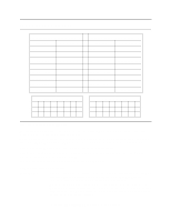
13.33 Standby (E2h/96h) Command Block Output Registers Register 7 6 5 4 3 2 1 0 Data Feature Sector Count V V V V V V V V Sector Number Cylinder Low Cylinder High Device/Head 1 - 1 D - - - - Command 1 1 1 0 0 0 1 0 Command Block Input Registers Register 7 6 5 4 3 2 1 0 Data Error see below Sector Count Sector Number Cylinder Low Cylinder High Device/Head Status see below Error Register 76543210 CRC UNC 0 IDN 0 ABT T0N AMN 00000V00 Status Register 7 6 5 4 3 2 10 BSY RDY DF DSC DRQ COR IDX ERR 0 V 0 V - 0 -V Figure 122. Standby command (E2h/96h) The Standby command causes the device to enter the Standby Mode immediately and to set the auto power down time-out parameter (standby timer). When this command is issued, the device confirms the completion of the cached write commands before it asserts the INTRQ. Following the INTRQ the interface remains active and the device is spun down. If the device is already spun down, the spin down sequence is not executed. During the Standby mode the device will respond to commands, however there will be a delay while waiting for the spindle to reach operating speed. The timer starts counting down when the device returns to Idle mode. Output Parameters To The Device Sector Count The Time-out Parameter. If it is zero the time-out interval (Standby Timer) is NOT disabled but is automatically set to 109 minutes. If it is other than zero the time-out interval is set for (Time-out Parameter × 5) seconds. When the automatic power down sequence is enabled, the device will enter the Standby mode automatically if the time-out interval expires with no device access from the host. The time-out interval will be reinitialized if there is a device access before the time-out interval expires. Travelstar 32GH/30GT/20GN hard disk drive specifications 176
-
 1
1 -
2
-
3
-
4
-
5
-
6
-
7
-
8
-
9
-
10
-
11
-
12
-
13
-
14
-
15
-
16
-
17
-
18
-
19
-
20
-
21
-
22
-
23
-
24
-
25
-
26
-
27
-
28
-
29
-
30
-
31
-
32
-
33
-
34
-
35
-
36
-
37
-
38
-
39
-
40
-
41
-
42
-
43
-
44
-
45
-
46
-
47
-
48
-
49
-
50
-
51
-
52
-
53
-
54
-
55
-
56
-
57
-
58
-
59
-
60
-
61
-
62
-
63
-
64
-
65
-
66
-
67
-
68
-
69
-
70
-
71
-
72
-
73
-
74
-
75
-
76
-
77
-
78
-
79
-
80
-
81
-
82
-
83
-
84
-
85
-
86
-
87
-
88
-
89
-
90
-
91
-
92
-
93
-
94
-
95
-
96
-
97
-
98
-
99
-
100
-
101
-
102
-
103
-
104
-
105
-
106
-
107
-
108
-
109
-
110
-
111
-
112
-
113
-
114
-
115
-
116
-
117
-
118
-
119
-
120
-
121
-
122
-
123
-
124
-
125
-
126
-
127
-
128
-
129
-
130
-
131
-
132
-
133
-
134
-
135
-
136
-
137
-
138
-
139
-
140
-
141
-
142
-
143
-
144
-
145
-
146
-
147
-
148
-
149
-
150
-
151
-
152
-
153
-
154
-
155
-
156
-
157
-
158
-
159
-
160
-
161
-
162
-
163
-
164
-
165
-
166
-
167
-
168
-
169
-
170
-
171
-
172
-
173
-
174
-
175
-
176
-
177
-
178
-
179
-
180
-
181
-
182
-
183
-
184
-
 185
185 -
 186
186 -
 187
187 -
 188
188 -
 189
189 -
 190
190 -
 191
191 -
 192
192 -
 193
193 -
 194
194 -
 195
195 -
196
-
197
-
198
-
199
-
200
-
201
-
202
-
203
-
204
-
205
-
206
-
207
-
208
-
209
-
210
-
211
 |
 |
