IBM DJSA-210 Hard Drive Specifications - Page 57
Signal descriptions, Read Operation, Conventional Definition, Special Definition, for Ultra DMA
 |
View all IBM DJSA-210 manuals
Add to My Manuals
Save this manual to your list of manuals |
Page 57 highlights
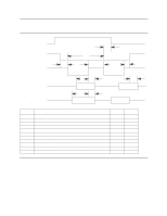
Write Operation Read Operation Special Definition (for Ultra DMA) -DDMARDY HSTROBE STOP -HDMARDY DSTROBE STOP Conventional Definition IORDY -DIOR -DIOW -DIOR IORDY -DIOW Figure 34. Special signal definitions for Ultra DMA 7.4 Signal descriptions DD00-DD15 A 16-bit bi-directional data bus between the host and the HDD. The lower 8 lines, DD00-07, are used for Register and ECC access. All 16 lines, DD00-15, are used for data transfer. These are 3-state lines with 24 mA current sink capability. DA00-DA02 These are addresses used to select the individual register in the HDD. -CS0 The chip select signal generated from the Host address bus. When active, one of the Command Block Registers [Data, Error (Features when written), Sector Count, Sector Number, Cylinder Low, Cylinder High, Drive/Head and Status (Command when written) register] can be selected. -CS1 The chip select signal generated from the Host address bus. When active, one of the Control Block Registers [Alternate Status (Device Control when written) and Drive Address register] can be selected. -RESET This line is used to reset the HDD. It shall be kept at a Low logic state during power up and kept High thereafter. -DIOW The rising edge of this signal holds data from the data bus to a register or data register of the HDD. -DIOR When this signal is low it enables data from a register or data register of the drive onto the data bus. The data on the bus shall be latched on the rising edge of -DIOR. INTRQ The interrupt is enabled only when the drive is selected and the host activates the -IEN bit in the Device Control Register. Otherwise, this signal is in high impedance state regardless of the state of the IRQ bit. The interrupt is set when the IRQ bit is set by the drive CPU. The IRQ is reset to zero by a host read of the status register or a write to the Command Register. This signal is a 3-state line with 24 mA of sink capability. Travelstar 32GH/30GT/20GN hard disk drive specifications 43
-
 1
1 -
2
-
3
-
4
-
5
-
6
-
7
-
8
-
9
-
10
-
11
-
12
-
13
-
14
-
15
-
16
-
17
-
18
-
19
-
20
-
21
-
22
-
23
-
24
-
25
-
26
-
27
-
28
-
29
-
30
-
31
-
32
-
33
-
34
-
35
-
36
-
37
-
38
-
39
-
40
-
41
-
42
-
43
-
44
-
45
-
46
-
47
-
48
-
49
-
50
-
51
-
 52
52 -
 53
53 -
 54
54 -
 55
55 -
 56
56 -
 57
57 -
 58
58 -
 59
59 -
 60
60 -
 61
61 -
 62
62 -
63
-
64
-
65
-
66
-
67
-
68
-
69
-
70
-
71
-
72
-
73
-
74
-
75
-
76
-
77
-
78
-
79
-
80
-
81
-
82
-
83
-
84
-
85
-
86
-
87
-
88
-
89
-
90
-
91
-
92
-
93
-
94
-
95
-
96
-
97
-
98
-
99
-
100
-
101
-
102
-
103
-
104
-
105
-
106
-
107
-
108
-
109
-
110
-
111
-
112
-
113
-
114
-
115
-
116
-
117
-
118
-
119
-
120
-
121
-
122
-
123
-
124
-
125
-
126
-
127
-
128
-
129
-
130
-
131
-
132
-
133
-
134
-
135
-
136
-
137
-
138
-
139
-
140
-
141
-
142
-
143
-
144
-
145
-
146
-
147
-
148
-
149
-
150
-
151
-
152
-
153
-
154
-
155
-
156
-
157
-
158
-
159
-
160
-
161
-
162
-
163
-
164
-
165
-
166
-
167
-
168
-
169
-
170
-
171
-
172
-
173
-
174
-
175
-
176
-
177
-
178
-
179
-
180
-
181
-
182
-
183
-
184
-
185
-
186
-
187
-
188
-
189
-
190
-
191
-
192
-
193
-
194
-
195
-
196
-
197
-
198
-
199
-
200
-
201
-
202
-
203
-
204
-
205
-
206
-
207
-
208
-
209
-
210
-
211
 |
 |
