IC Realtime HDVR-MX0402-1U5MP-AI2-WEB Product Manual - Page 33
Typical Connection Diagram, 2 Connecting to Video and Audio Input and Output
 |
View all IC Realtime HDVR-MX0402-1U5MP-AI2-WEB manuals
Add to My Manuals
Save this manual to your list of manuals |
Page 33 highlights
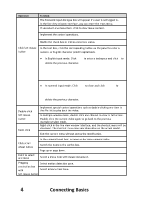
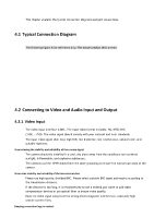
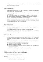
This chapter explains the typical connection diagrams and port connections. 4.1 Typical Connection Diagram The following figure is for reference only. The actual product shall prevail. 4.2 Connecting to Video and Audio Input and Output 4.2.1 Video Input The video input interface is BNC. The input video format includes: PAL/NTSC BNC (1.0VP-P, 75Ω). The video signal should comply with your national and local standards. The input video signal shall have high SNR, low distortion; low interference, natural color, and suitable lightness. Guaranteeing the stability and reliability of the camera signal The camera should be installed in a cool, dry place away from the conditions such as direct sunlight, inflammable, and explosive substances. The cameras and the HDVR should have the same grounding to ensure the normal operation of the camera. Guarantee stability and reliability of the transmission line Please use high-quality, shielded BNC. Please select suitable BNC types and models according to the transmission distance. If the distance is too long, it is recommended to use a twisted pair cable to add video compensation devices or use optical fiber to ensure video quality. Keep the video signal away from the strong electromagnetic interference, especially high tension current lines. Keeping connection lugs in contact
-
 1
1 -
2
-
3
-
4
-
5
-
6
-
7
-
8
-
9
-
10
-
11
-
12
-
13
-
14
-
15
-
16
-
17
-
18
-
19
-
20
-
21
-
22
-
23
-
24
-
25
-
26
-
27
-
 28
28 -
 29
29 -
 30
30 -
 31
31 -
 32
32 -
 33
33 -
 34
34 -
 35
35 -
 36
36 -
 37
37 -
 38
38 -
39
-
40
-
41
-
42
-
43
-
44
-
45
-
46
-
47
-
48
-
49
-
50
-
51
-
52
-
53
-
54
-
55
-
56
-
57
-
58
-
59
-
60
-
61
-
62
-
63
-
64
-
65
-
66
-
67
-
68
-
69
-
70
-
71
-
72
-
73
-
74
-
75
-
76
-
77
-
78
-
79
-
80
-
81
-
82
-
83
-
84
-
85
-
86
-
87
-
88
-
89
-
90
-
91
-
92
-
93
-
94
-
95
-
96
-
97
-
98
-
99
-
100
-
101
-
102
-
103
-
104
-
105
-
106
-
107
-
108
-
109
-
110
-
111
-
112
-
113
-
114
-
115
-
116
-
117
-
118
-
119
-
120
-
121
-
122
-
123
-
124
-
125
-
126
-
127
-
128
-
129
-
130
-
131
-
132
-
133
-
134
-
135
-
136
-
137
-
138
-
139
-
140
-
141
-
142
-
143
-
144
-
145
-
146
-
147
-
148
-
149
-
150
-
151
-
152
-
153
-
154
-
155
-
156
-
157
-
158
-
159
-
160
-
161
-
162
-
163
-
164
-
165
-
166
-
167
-
168
-
169
-
170
-
171
-
172
-
173
-
174
-
175
-
176
-
177
-
178
-
179
-
180
-
181
-
182
-
183
-
184
-
185
-
186
-
187
-
188
-
189
-
190
-
191
-
192
-
193
-
194
-
195
-
196
-
197
-
198
-
199
-
200
-
201
-
202
-
203
-
204
-
205
-
206
-
207
-
208
-
209
-
210
-
211
-
212
-
213
-
214
-
215
-
216
-
217
-
218
-
219
-
220
-
221
-
222
-
223
-
224
-
225
-
226
-
227
-
228
-
229
-
230
-
231
-
232
-
233
-
234
-
235
-
236
-
237
-
238
-
239
-
240
-
241
-
242
-
243
-
244
-
245
-
246
-
247
-
248
-
249
-
250
-
251
-
252
-
253
 |
 |
