Icom IC-7610 Instruction Manual advanced - Page 84
OTHER FUNCTIONS, RF Direct Sampling System
 |
View all Icom IC-7610 manuals
Add to My Manuals
Save this manual to your list of manuals |
Page 84 highlights
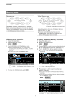
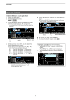
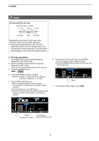
11. OTHER FUNCTIONS RF Direct Sampling System The IC-7610 employs an RF direct sampling system and has 2 completely independent and identical receiver circuits for the Main and Sub bands from the antenna to the AF output. RF signals are directly converted to digital data and processed in a Field Programmable Gate Array (FPGA) with Icom's state of the SDR technology. The RF signals are sent to the A/D converter, resulting in digital signal, then is processed by the FPGA to be restored to an analog audio signal according to the receive mode. This system is a leading technology marking an epoch in amateur radio. In the Direct Sampling System, there is no local oscillator or mixer circuits that are used in ordinary super heterodyne systems. That makes the received signal less distorted in the amplification stage, resulting a higher image response received signal. In the transmit circuit, since the transmit signal is generated by the FPGA regardless of the type of emission, a pure high C/N ratio transmit signal is obtained. ANT 1 DIGI-SEL BPF ANT 2 Main band Sub band DIGI-SEL BPF Demodulation circuit A/D FPGA A/D EXT-SP A D/A EXT-SP B D/A 78
-
 1
1 -
2
-
3
-
4
-
5
-
6
-
7
-
8
-
9
-
10
-
11
-
12
-
13
-
14
-
15
-
16
-
17
-
18
-
19
-
20
-
21
-
22
-
23
-
24
-
25
-
26
-
27
-
28
-
29
-
30
-
31
-
32
-
33
-
34
-
35
-
36
-
37
-
38
-
39
-
40
-
41
-
42
-
43
-
44
-
45
-
46
-
47
-
48
-
49
-
50
-
51
-
52
-
53
-
54
-
55
-
56
-
57
-
58
-
59
-
60
-
61
-
62
-
63
-
64
-
65
-
66
-
67
-
68
-
69
-
70
-
71
-
72
-
73
-
74
-
75
-
76
-
77
-
78
-
 79
79 -
 80
80 -
 81
81 -
 82
82 -
 83
83 -
 84
84 -
 85
85 -
 86
86 -
 87
87 -
 88
88 -
 89
89 -
90
-
91
-
92
-
93
-
94
-
95
-
96
-
97
-
98
-
99
-
100
-
101
 |
 |
