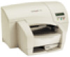
Lexmark J110 Service Manual - Page 80
Operator Panel (Buttons) Service Check
 |
View all Lexmark J110 manuals
Add to My Manuals
Save this manual to your list of manuals |
Page 80 highlights
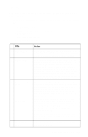
4085-001 Operator Panel (Buttons) Service Check FRU 1 Operator Panel Assembly 2 Engine Board Operator Panel Assembly Action If any button fails the button test, replace the operator panel assembly. See "Button Test" on page 3-23 . With the operator panel connected to the engine board, be sure the voltage at (J4) pins 1, 2, 3 and 5 measures +5 V dc. If the voltage is incorrect, replace the engine board. If the voltage is correct, check the continuity of the operator panel cable. Replace the operator panel cable if continuity is incorrect. If correct, replace the operator panel assembly. 2-58 Service Manual
-
 1
1 -
2
-
3
-
4
-
5
-
6
-
7
-
8
-
9
-
10
-
11
-
12
-
13
-
14
-
15
-
16
-
17
-
18
-
19
-
20
-
21
-
22
-
23
-
24
-
25
-
26
-
27
-
28
-
29
-
30
-
31
-
32
-
33
-
34
-
35
-
36
-
37
-
38
-
39
-
40
-
41
-
42
-
43
-
44
-
45
-
46
-
47
-
48
-
49
-
50
-
51
-
52
-
53
-
54
-
55
-
56
-
57
-
58
-
59
-
60
-
61
-
62
-
63
-
64
-
65
-
66
-
67
-
68
-
69
-
70
-
71
-
72
-
73
-
74
-
 75
75 -
 76
76 -
 77
77 -
 78
78 -
 79
79 -
 80
80 -
 81
81 -
 82
82 -
 83
83 -
 84
84 -
 85
85 -
86
-
87
-
88
-
89
-
90
-
91
-
92
-
93
-
94
-
95
-
96
-
97
-
98
-
99
-
100
-
101
-
102
-
103
-
104
-
105
-
106
-
107
-
108
-
109
-
110
-
111
-
112
-
113
-
114
-
115
-
116
-
117
-
118
-
119
-
120
-
121
-
122
-
123
-
124
-
125
-
126
-
127
-
128
-
129
-
130
-
131
-
132
-
133
-
134
-
135
-
136
-
137
-
138
-
139
-
140
-
141
-
142
-
143
-
144
-
145
-
146
-
147
-
148
-
149
-
150
-
151
-
152
-
153
-
154
-
155
-
156
-
157
-
158
-
159
-
160
-
161
-
162
-
163
-
164
-
165
-
166
-
167
-
168
-
169
-
170
-
171
-
172
-
173
-
174
-
175
-
176
-
177
-
178
-
179
-
180
-
181
-
182
-
183
-
184
-
185
-
186
-
187
-
188
-
189
-
190
-
191
-
192
-
193
-
194
-
195
-
196
-
197
-
198
-
199
-
200
-
201
-
202
-
203
-
204
-
205
-
206
-
207
-
208
-
209
-
210
-
211
-
212
-
213
-
214
-
215
-
216
-
217
-
218
-
219
-
220
-
221
-
222
-
223
-
224
-
225
-
226
-
227
-
228
-
229
-
230
-
231
-
232
-
233
-
234
-
235
-
236
-
237
-
238
-
239
-
240
-
241
-
242
-
243
-
244
-
245
-
246
-
247
-
248
 |
 |

2-58
Service Manual
4085-001
Operator Panel (Buttons) Service Check
FRU
Action
1
Operator Panel
Assembly
If any button fails the button test, replace the
operator panel assembly. See
“Button Test” on
page 3-23
.
2
Engine Board
Operator Panel
Assembly
With the operator panel connected to the engine
board, be sure the voltage at (J4) pins 1, 2, 3 and
5 measures +5 V dc. If the voltage is incorrect,
replace the engine board. If the voltage is correct,
check the continuity of the operator panel cable.
Replace the operator panel cable if continuity is
incorrect. If correct, replace the operator panel
assembly.