Lexmark J110 Service Manual - Page 86
RIP Card Service Check, Parallel or USB
 |
View all Lexmark J110 manuals
Add to My Manuals
Save this manual to your list of manuals |
Page 86 highlights
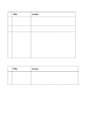
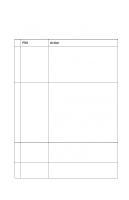
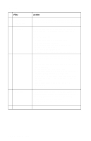
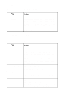
4085-001 FRU 2 Power Line Cord 3 Power Switch 4 Power Supply Action Check the power line cord for damage. Check the continuity of the line cord and replace if necessary. Check the continuity on the power switch. If incorrect, replace the power switch. With the power switch turned on, verify the voltage readings at RIP card connector (J1) and engine board connector (J1). The RIP card voltage at J1-1 and J1-2 should be approximately +5 V dc at each pin. Check the engine board connector (J1) voltage to verify that J1-3 and J1-4 have approximately +35 V and J1-11, J2-12 read 5 volts each. Note: If any of the voltage readings are not correct, replace the power supply. RIP Card Service Check FRU 1 Parallel or USB does not work Action Check parallel or USB cables and J2 connection. If OK, check the voltage reading at connector J1 for +5 V dc at pins 1 and 2. If the voltage reading is correct, replace the RIP card. If voltage is not correct, replace the power supply. 2-64 Service Manual
-
 1
1 -
2
-
3
-
4
-
5
-
6
-
7
-
8
-
9
-
10
-
11
-
12
-
13
-
14
-
15
-
16
-
17
-
18
-
19
-
20
-
21
-
22
-
23
-
24
-
25
-
26
-
27
-
28
-
29
-
30
-
31
-
32
-
33
-
34
-
35
-
36
-
37
-
38
-
39
-
40
-
41
-
42
-
43
-
44
-
45
-
46
-
47
-
48
-
49
-
50
-
51
-
52
-
53
-
54
-
55
-
56
-
57
-
58
-
59
-
60
-
61
-
62
-
63
-
64
-
65
-
66
-
67
-
68
-
69
-
70
-
71
-
72
-
73
-
74
-
75
-
76
-
77
-
78
-
79
-
80
-
 81
81 -
 82
82 -
 83
83 -
 84
84 -
 85
85 -
 86
86 -
 87
87 -
 88
88 -
 89
89 -
 90
90 -
 91
91 -
92
-
93
-
94
-
95
-
96
-
97
-
98
-
99
-
100
-
101
-
102
-
103
-
104
-
105
-
106
-
107
-
108
-
109
-
110
-
111
-
112
-
113
-
114
-
115
-
116
-
117
-
118
-
119
-
120
-
121
-
122
-
123
-
124
-
125
-
126
-
127
-
128
-
129
-
130
-
131
-
132
-
133
-
134
-
135
-
136
-
137
-
138
-
139
-
140
-
141
-
142
-
143
-
144
-
145
-
146
-
147
-
148
-
149
-
150
-
151
-
152
-
153
-
154
-
155
-
156
-
157
-
158
-
159
-
160
-
161
-
162
-
163
-
164
-
165
-
166
-
167
-
168
-
169
-
170
-
171
-
172
-
173
-
174
-
175
-
176
-
177
-
178
-
179
-
180
-
181
-
182
-
183
-
184
-
185
-
186
-
187
-
188
-
189
-
190
-
191
-
192
-
193
-
194
-
195
-
196
-
197
-
198
-
199
-
200
-
201
-
202
-
203
-
204
-
205
-
206
-
207
-
208
-
209
-
210
-
211
-
212
-
213
-
214
-
215
-
216
-
217
-
218
-
219
-
220
-
221
-
222
-
223
-
224
-
225
-
226
-
227
-
228
-
229
-
230
-
231
-
232
-
233
-
234
-
235
-
236
-
237
-
238
-
239
-
240
-
241
-
242
-
243
-
244
-
245
-
246
-
247
-
248
 |
 |
