Netgear STM300 STM 150-300-600 Reference Manual (PDF) - Page 18
Front Panel STM600, Status LED, HDD LED, USB port, Power LED, Console port, Mgmt port
 |
UPC - 606449062458
View all Netgear STM300 manuals
Add to My Manuals
Save this manual to your list of manuals |
Page 18 highlights
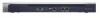
ProSecure Web/Email Security Threat Management (STM) Appliance Front Panel STM600 The following figure shows the front panel ports and LEDs of the STM600: 2) Power LED 7) Pair 1 LEDs 3) Status LED 6) Mgmt port 8) Pair 2 LEDs Figure 4. 1) Console port 5) USB port 8) Pair 2 ports 4) HDD LED 7) Pair 1 ports From left to right, the STM600's front panel shows the following ports and LEDs: 1. Console port. Port for connecting to an optional console terminal. The ports has a DB9 male connector. The default baud rate is 9600 K. The pinouts are (2) Tx, (3) Rx, (5) and (7) Gnd. 2. Power LED. 3. Status LED. 4. Hard drive (HDD) LED. 5. One nonfunctioning USB port. This port is included for future management enhancements. The port is currently not operable on any STM model. 6. Dedicated management (Mgmt) Gigabit Ethernet port with an RJ-45 connector. 7. Pair 1 uplink (WAN) and downlink (LAN) Gigabit Ethernet ports with RJ-45 connectors, left LEDs, and right LEDs. 8. Pair 2 uplink (WAN) and downlink (LAN) Gigabit Ethernet ports with RJ-45 connectors, left LEDs, and right LEDs. Note: All Gigabit Ethernet ports provide switched N-way, automatic speed-negotiating, auto MDI/MDIX technology. 18 | Chapter 1. Introduction
-
 1
1 -
2
-
3
-
4
-
5
-
6
-
7
-
8
-
9
-
10
-
11
-
12
-
 13
13 -
 14
14 -
 15
15 -
 16
16 -
 17
17 -
 18
18 -
 19
19 -
 20
20 -
 21
21 -
 22
22 -
 23
23 -
24
-
25
-
26
-
27
-
28
-
29
-
30
-
31
-
32
-
33
-
34
-
35
-
36
-
37
-
38
-
39
-
40
-
41
-
42
-
43
-
44
-
45
-
46
-
47
-
48
-
49
-
50
-
51
-
52
-
53
-
54
-
55
-
56
-
57
-
58
-
59
-
60
-
61
-
62
-
63
-
64
-
65
-
66
-
67
-
68
-
69
-
70
-
71
-
72
-
73
-
74
-
75
-
76
-
77
-
78
-
79
-
80
-
81
-
82
-
83
-
84
-
85
-
86
-
87
-
88
-
89
-
90
-
91
-
92
-
93
-
94
-
95
-
96
-
97
-
98
-
99
-
100
-
101
-
102
-
103
-
104
-
105
-
106
-
107
-
108
-
109
-
110
-
111
-
112
-
113
-
114
-
115
-
116
-
117
-
118
-
119
-
120
-
121
-
122
-
123
-
124
-
125
-
126
-
127
-
128
-
129
-
130
-
131
-
132
-
133
-
134
-
135
-
136
-
137
-
138
-
139
-
140
-
141
-
142
-
143
-
144
-
145
-
146
-
147
-
148
-
149
-
150
-
151
-
152
-
153
-
154
-
155
-
156
-
157
-
158
-
159
-
160
-
161
-
162
-
163
-
164
-
165
-
166
-
167
-
168
-
169
-
170
-
171
-
172
-
173
-
174
-
175
-
176
-
177
-
178
-
179
-
180
-
181
-
182
-
183
-
184
-
185
-
186
-
187
-
188
-
189
-
190
-
191
-
192
-
193
-
194
-
195
-
196
-
197
-
198
-
199
-
200
-
201
-
202
-
203
-
204
-
205
-
206
-
207
-
208
-
209
-
210
-
211
-
212
-
213
-
214
-
215
-
216
-
217
-
218
-
219
-
220
-
221
-
222
-
223
-
224
-
225
-
226
-
227
-
228
-
229
-
230
-
231
-
232
-
233
-
234
-
235
-
236
-
237
-
238
-
239
-
240
-
241
-
242
-
243
-
244
-
245
-
246
-
247
-
248
-
249
-
250
-
251
-
252
-
253
-
254
-
255
-
256
-
257
-
258
-
259
-
260
-
261
 |
 |
