Oki X400 X400 Programming Command Manual - Page 12
Command Code Reference
 |
View all Oki X400 manuals
Add to My Manuals
Save this manual to your list of manuals |
Page 12 highlights
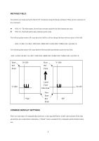
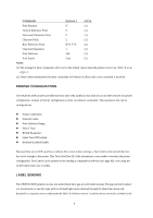
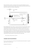
bottom of the label liner or tag. The eye-mark must not reflect more than 12% of the light. Since the same receiving sensor is used for all three types of sensing, it must be calibrated with the media that will be used. The ribbon must be installed while the calibration is being performed. Max Left Margin 4mm Print Head Gap, Notch or Bar Height Sensing Width: 8mm 2mm~25mm Adjustable Position Sensor Min Label Width 13mm Min Label Pitch 10mm When calibrating the printer sensors, the gap or eye-mark sensor type must be selected first using the CI command and then the Direct Thermal or Thermal Transfer print mode must be specified with an CP command. These two commands are followed by an CA Calibrate command to instruct the printer to perform the calibration procedure. The resulting calibration values are stored in the printer and used until the unit is recalibrated. A separated value is stored for direct thermal or thermal transfer modes because the settings will differ significantly because of the inclusion of the ribbon for thermal transfer. For example, the following command string will calibrate the printer in the thermal transfer mode for gap sensing: ACP1CI2CAZ COMMAND CODE PAGE REFERENCE This section contains all the printer Command Codes. The commands must be sent to the printer in an organized fashion in order for the label(s) to print. The purpose of this section is to: 10
-
 1
1 -
2
-
3
-
4
-
5
-
6
-
 7
7 -
 8
8 -
 9
9 -
 10
10 -
 11
11 -
 12
12 -
 13
13 -
 14
14 -
 15
15 -
 16
16 -
 17
17 -
18
-
19
-
20
-
21
-
22
-
23
-
24
-
25
-
26
-
27
-
28
-
29
-
30
-
31
-
32
-
33
-
34
-
35
-
36
-
37
-
38
-
39
-
40
-
41
-
42
-
43
-
44
-
45
-
46
-
47
-
48
-
49
-
50
-
51
-
52
-
53
-
54
-
55
-
56
-
57
-
58
-
59
-
60
-
61
-
62
-
63
-
64
-
65
-
66
-
67
-
68
-
69
-
70
-
71
-
72
-
73
-
74
-
75
-
76
-
77
-
78
-
79
-
80
-
81
-
82
-
83
-
84
-
85
-
86
-
87
-
88
-
89
-
90
-
91
-
92
-
93
-
94
-
95
-
96
-
97
-
98
-
99
-
100
-
101
-
102
-
103
-
104
-
105
-
106
-
107
-
108
-
109
-
110
-
111
-
112
-
113
-
114
-
115
-
116
-
117
-
118
-
119
-
120
-
121
-
122
-
123
-
124
-
125
-
126
-
127
-
128
-
129
-
130
-
131
-
132
-
133
-
134
-
135
-
136
-
137
 |
 |
