Yamaha PM5D Owner's Manual - Page 140
Controlling the channels assigned to DCA faders, Assign channels to other layers in the same
 |
View all Yamaha PM5D manuals
Add to My Manuals
Save this manual to your list of manuals |
Page 140 highlights
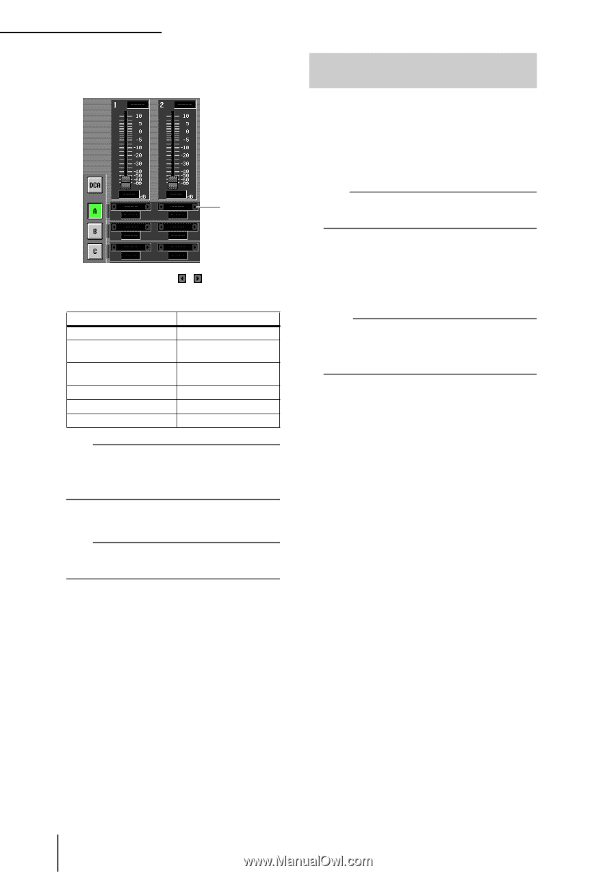
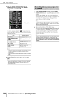
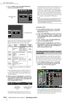
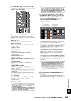
19 Other functions 2 Use the channel selection boxes for the desired layer (A-F) to select the channel assigned to each fader 1-8. Channel selection box To select a channel, click the / buttons located at the left and right of each box. You can choose from the following channels. Item CH 1-CH48 STIN1L/STIN1R-STIN4L/ STIN4R FXRTN1L/FXRTN1R- FXRTN4L/FXRTN4R MIX 1-MIX24 MTRX1-MTRX8 DCA1-8 Selected channel Input channel 1-48 ST IN channel 1-4 L or R FX RTN channel 1-4 L or R MIX channel 1-24 MATRIX channel 1-8 DCA fader 1-8 Hint • If an input channel or a DCA fader 1-8 is selected, the channel name is displayed immediately below the channel selection box. • Input channels and output channels can coexist in the same layer. 3 Assign channels to other layers in the same way. Hint Fader Assign settings are not saved in the scene. If desired, you can save these settings on a memory card as DCA FADER MODE data. Controlling the channels assigned to DCA faders 1 In the FADER MODE section, use the FADER MODE [A]-[F] keys to select the layer you want to use. The key LED will light, and the corresponding layer will become active. If input channels are assigned to the DCA faders, the channel names will appear in the name indicators of the DCA strip. Hint You can also switch layers from within the FADER ASSIGN screen. This screen also shows the values of the DCA faders and their approximate positions. 2 Operate the faders of the DCA strip. The level of the corresponding channels will change. If a channel assigned to a DCA fader is paired (or if one side of a stereo channel is assigned), the level of the other paired channel (or the other side of the stereo channel) will follow. Note When a FADER MODE [A]-[F] key is on, and channels other than DCA channels are assigned to the DCA faders, the [MUTE] keys of the DCA channel strip are inactive. However, the [CUE] keys can be used to cue-monitor the corresponding channel. 140 PM5D/PM5D-RH Owner's Manual Operating section
-
 1
1 -
2
-
3
-
4
-
5
-
6
-
7
-
8
-
9
-
10
-
11
-
12
-
13
-
14
-
15
-
16
-
17
-
18
-
19
-
20
-
21
-
22
-
23
-
24
-
25
-
26
-
27
-
28
-
29
-
30
-
31
-
32
-
33
-
34
-
35
-
36
-
37
-
38
-
39
-
40
-
41
-
42
-
43
-
44
-
45
-
46
-
47
-
48
-
49
-
50
-
51
-
52
-
53
-
54
-
55
-
56
-
57
-
58
-
59
-
60
-
61
-
62
-
63
-
64
-
65
-
66
-
67
-
68
-
69
-
70
-
71
-
72
-
73
-
74
-
75
-
76
-
77
-
78
-
79
-
80
-
81
-
82
-
83
-
84
-
85
-
86
-
87
-
88
-
89
-
90
-
91
-
92
-
93
-
94
-
95
-
96
-
97
-
98
-
99
-
100
-
101
-
102
-
103
-
104
-
105
-
106
-
107
-
108
-
109
-
110
-
111
-
112
-
113
-
114
-
115
-
116
-
117
-
118
-
119
-
120
-
121
-
122
-
123
-
124
-
125
-
126
-
127
-
128
-
129
-
130
-
131
-
132
-
133
-
134
-
 135
135 -
 136
136 -
 137
137 -
 138
138 -
 139
139 -
 140
140 -
 141
141 -
 142
142 -
 143
143 -
 144
144 -
 145
145 -
146
-
147
-
148
-
149
-
150
-
151
-
152
-
153
-
154
-
155
-
156
-
157
-
158
-
159
-
160
-
161
-
162
-
163
-
164
-
165
-
166
-
167
-
168
-
169
-
170
-
171
-
172
-
173
-
174
-
175
-
176
-
177
-
178
-
179
-
180
-
181
-
182
-
183
-
184
-
185
-
186
-
187
-
188
-
189
-
190
-
191
-
192
-
193
-
194
-
195
-
196
-
197
-
198
-
199
-
200
-
201
-
202
-
203
-
204
-
205
-
206
-
207
-
208
-
209
-
210
-
211
-
212
-
213
-
214
-
215
-
216
-
217
-
218
-
219
-
220
-
221
-
222
-
223
-
224
-
225
-
226
-
227
-
228
-
229
-
230
-
231
-
232
-
233
-
234
-
235
-
236
-
237
-
238
-
239
-
240
-
241
-
242
-
243
-
244
-
245
-
246
-
247
-
248
-
249
-
250
-
251
-
252
-
253
-
254
-
255
-
256
-
257
-
258
-
259
-
260
-
261
-
262
-
263
-
264
-
265
-
266
-
267
-
268
-
269
-
270
-
271
-
272
-
273
-
274
-
275
-
276
-
277
-
278
-
279
-
280
-
281
-
282
-
283
-
284
-
285
-
286
-
287
-
288
-
289
-
290
-
291
-
292
-
293
-
294
-
295
-
296
-
297
-
298
-
299
-
300
-
301
-
302
-
303
-
304
-
305
-
306
-
307
-
308
-
309
-
310
-
311
-
312
-
313
-
314
-
315
-
316
-
317
-
318
-
319
-
320
-
321
-
322
-
323
-
324
-
325
-
326
-
327
-
328
-
329
-
330
-
331
-
332
-
333
-
334
-
335
-
336
-
337
-
338
-
339
-
340
-
341
-
342
-
343
-
344
-
345
-
346
-
347
-
348
-
349
-
350
-
351
-
352
-
353
-
354
-
355
-
356
-
357
-
358
-
359
-
360
-
361
-
362
-
363
-
364
-
365
-
366
-
367
 |
 |