Yamaha PM5D Owner's Manual - Page 143
Using cascade connections, Basic settings for cascade connection, Cascade master
 |
View all Yamaha PM5D manuals
Add to My Manuals
Save this manual to your list of manuals |
Page 143 highlights
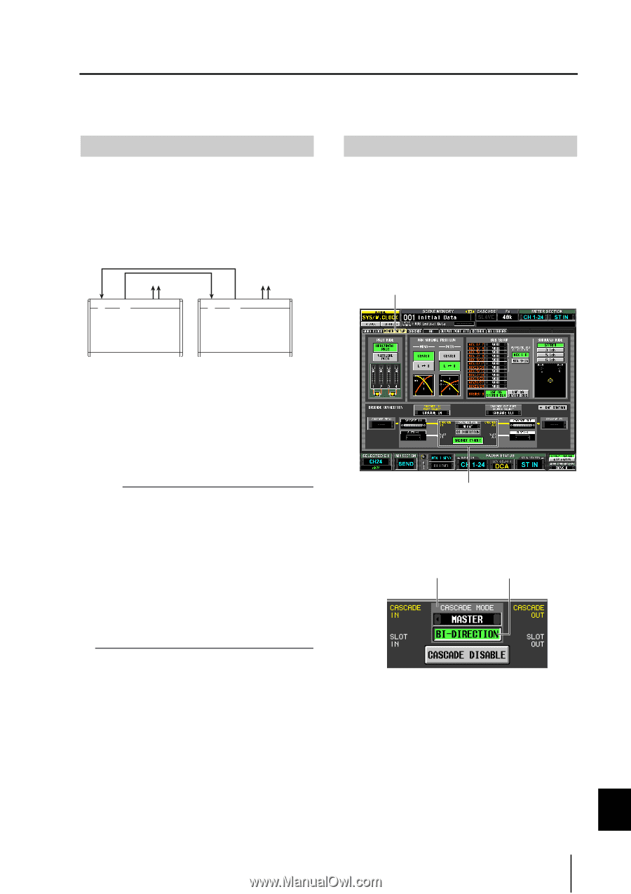
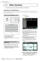
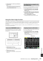
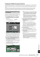
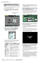
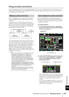
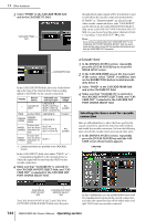
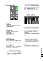
Using cascade connections Buses can be shared by cascade-connecting multiple PM5D units (up to four) or the PM5D with an external mixer (such as the Yamaha DM2000/02R96). When multiple PM5D units are cascade-connected, operations such as scene store/recall, cue/ solo, and dimmer can also be linked. Making cascade connections Here we will explain cascade connections and operation, using an example in which two PM5D units are cascadeconnected. To cascade-connect two PM5D units, connect the CASCADE IN connectors and CASCADE OUT connectors of the two units to each other. This allows the MIX bus, STEREO bus, and CUE bus output signals to be transmitted and received between the two units. CASCADE CASCADE IN OUT Audio signals of units A+B CASCADE CASCADE IN OUT Audio signals of units A+B PM5D A (cascade master) PM5D B (cascade slave) Basic settings for cascade connection Here we will explain the basic settings required for a bidirectional cascade connection between two PM5D units; we will provide separate explanations for the cascade master and the cascade slave. ❏ Cascade master 1 In the DISPLAY ACCESS section, repeatedly press the [SYS/W.CLOCK] key until the MIXER SETUP screen appears. MIXER SETUP If you want operations such as scene store/recall and cue/ solo to be linked between the two PM5D units, specify one unit as the cascade master and the other as the cascade slave. (This setting is made in the SYS/W.CLOCK function MIXER SETUP screen.) The PM5D assigned as the cascade master will output control signals (operational signals) via its CASCADE IN connector, and the PM5D assigned as the cascade slave will receive these signals via its CASCADE OUT connector. Hint • If you want to daisy-chain two to four PM5D units (i.e., connect the first unit's CASCADE OUT → second unit's CASCADE IN, and the second unit's CASCADE OUT → third unit's CASCADE IN. Up to four units can be connected.), you should assign the PM5D located last in the chain (the PM5D connected only via its CASCADE IN connector) as the cascade master, and the remaining PM5D units as cascade slaves (➥ p.204). • If you want to cascade-connect a PM5D with a Yamaha DM2000 or 02R96, connect the CASCADE OUT connector of the DM2000/02R96 to the CASCADE IN connector of the PM5D. However in this case, it is not possible to link operations. • If you want to cascade-connect the PM5D with any other external mixer, use I/O cards installed in slots 1-4 to send and receive the audio signals (➥ p.202). CASCADE MODE area 2 In the CASCADE MODE area at the lower part of the screen, select "MASTER". In addition, turn on the BI-DIRECTION button located immediately below it. CASCADE MODE area BI-DIRECTION button Other functions When multiple PM5D units are cascaded, the settings of the CASCADE MODE area specify whether the unit will operate as a cascade master (when "MASTER" is selected) or as a cascade slave (when "SLAVE" is selected). If you turn the BI-DIRECTION button on, the mixed audio signals of both cascade-connected PM5D units will be output from both units. 19 PM5D/PM5D-RH Owner's Manual Operating section 143
-
 1
1 -
2
-
3
-
4
-
5
-
6
-
7
-
8
-
9
-
10
-
11
-
12
-
13
-
14
-
15
-
16
-
17
-
18
-
19
-
20
-
21
-
22
-
23
-
24
-
25
-
26
-
27
-
28
-
29
-
30
-
31
-
32
-
33
-
34
-
35
-
36
-
37
-
38
-
39
-
40
-
41
-
42
-
43
-
44
-
45
-
46
-
47
-
48
-
49
-
50
-
51
-
52
-
53
-
54
-
55
-
56
-
57
-
58
-
59
-
60
-
61
-
62
-
63
-
64
-
65
-
66
-
67
-
68
-
69
-
70
-
71
-
72
-
73
-
74
-
75
-
76
-
77
-
78
-
79
-
80
-
81
-
82
-
83
-
84
-
85
-
86
-
87
-
88
-
89
-
90
-
91
-
92
-
93
-
94
-
95
-
96
-
97
-
98
-
99
-
100
-
101
-
102
-
103
-
104
-
105
-
106
-
107
-
108
-
109
-
110
-
111
-
112
-
113
-
114
-
115
-
116
-
117
-
118
-
119
-
120
-
121
-
122
-
123
-
124
-
125
-
126
-
127
-
128
-
129
-
130
-
131
-
132
-
133
-
134
-
135
-
136
-
137
-
 138
138 -
 139
139 -
 140
140 -
 141
141 -
 142
142 -
 143
143 -
 144
144 -
 145
145 -
 146
146 -
 147
147 -
 148
148 -
149
-
150
-
151
-
152
-
153
-
154
-
155
-
156
-
157
-
158
-
159
-
160
-
161
-
162
-
163
-
164
-
165
-
166
-
167
-
168
-
169
-
170
-
171
-
172
-
173
-
174
-
175
-
176
-
177
-
178
-
179
-
180
-
181
-
182
-
183
-
184
-
185
-
186
-
187
-
188
-
189
-
190
-
191
-
192
-
193
-
194
-
195
-
196
-
197
-
198
-
199
-
200
-
201
-
202
-
203
-
204
-
205
-
206
-
207
-
208
-
209
-
210
-
211
-
212
-
213
-
214
-
215
-
216
-
217
-
218
-
219
-
220
-
221
-
222
-
223
-
224
-
225
-
226
-
227
-
228
-
229
-
230
-
231
-
232
-
233
-
234
-
235
-
236
-
237
-
238
-
239
-
240
-
241
-
242
-
243
-
244
-
245
-
246
-
247
-
248
-
249
-
250
-
251
-
252
-
253
-
254
-
255
-
256
-
257
-
258
-
259
-
260
-
261
-
262
-
263
-
264
-
265
-
266
-
267
-
268
-
269
-
270
-
271
-
272
-
273
-
274
-
275
-
276
-
277
-
278
-
279
-
280
-
281
-
282
-
283
-
284
-
285
-
286
-
287
-
288
-
289
-
290
-
291
-
292
-
293
-
294
-
295
-
296
-
297
-
298
-
299
-
300
-
301
-
302
-
303
-
304
-
305
-
306
-
307
-
308
-
309
-
310
-
311
-
312
-
313
-
314
-
315
-
316
-
317
-
318
-
319
-
320
-
321
-
322
-
323
-
324
-
325
-
326
-
327
-
328
-
329
-
330
-
331
-
332
-
333
-
334
-
335
-
336
-
337
-
338
-
339
-
340
-
341
-
342
-
343
-
344
-
345
-
346
-
347
-
348
-
349
-
350
-
351
-
352
-
353
-
354
-
355
-
356
-
357
-
358
-
359
-
360
-
361
-
362
-
363
-
364
-
365
-
366
-
367
 |
 |