Yamaha PM5D Owner's Manual - Page 202
CASCADE FROM Source when cascade, connected, CASCADE IN PORT SELECT, CASCADE IN, SLOT 4
 |
View all Yamaha PM5D manuals
Add to My Manuals
Save this manual to your list of manuals |
Page 202 highlights
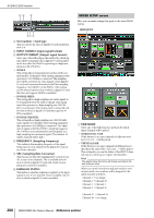
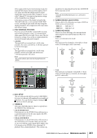
SYS/W.CLOCK function • 6.1ch This mode uses seven channels: 5.1ch with the addition of Bs (rear center). LFE (subwoofer) L (front left) C (front center) R (front right) Ls (rear left) Bs (rear center) Rs (rear right) Hint The graphic below the buttons will change according to the mode you select. 8 J N 7 K ML 9 G CASCADE FROM (Source when cascadeconnected) Select one of the following as the external device that is sending audio signals to the PM5D via a cascade connection. Display Source device Available cas- Paramecade input port ter linkage - PM5D Cascade disabled another PM5D CASCADE IN, SLOT 3/4, SLOT 1-4 [CH1-8], SLOT 1-4 [CH9-16] CASCADE IN Not possible Possible*1 DM2000 YAMAHA DM2000 /02R96 or 02R96 CASCADE IN MIXER [30BUS] A mixer other than the above (maximum 30 bus) SLOT 3/4, SLOT 1-4 [CH1-8], SLOT 1-4 [CH9-16] Not possible MIXER [16BUS] A mixer other than the above (maximum 16 bus) SLOT 4 *1. Linked parameters are specified in the CASCADE screen. H CASCADE IN PORT SELECT Select one of the following as the port that will receive the audio signals from the cascade-connected device. Hint • If you select a choice other than CASCADE IN, the signal from the slot will be assigned to the cascade input, and the signal from the CASCADE IN connector will be assigned to the corresponding slot input. • The signal assigned from the CASCADE IN connector to the slot input can be used as a patch source in the IN PATCH screen. • CASCADE IN Up to 30 channels of audio signals can be received from another PM5D via the rear panel CASCADE IN connector. If PM5D is selected as the cascade source (7), control signals for parameter linkage will also be transmitted and received. • SLOT 4 Up to 16 channels of audio signals can be received via input channels 1-16 of an I/O card installed in slot 4 of the rear panel. If you choose this setting, the signals from the CASCADE IN connector (channels 1-16) will be assigned to channels 1-16 of the SLOT IN 4 port instead. CH 1-16 SLOT 4 16 channels CASCADE IN CH 1-16 SLOT 1-3 CH 1-16 CASCADE IN 16 channels SLOT IN 1 (CH 1-16) SLOT IN 2 (CH 1-16) SLOT IN 3 (CH 1-16) SLOT IN 4 (CH 1-16) • SLOT 3/4 Up to 30 channels of audio signals can be received via input channels 1-16 of I/O cards installed in slots 3 and 4. (Since channels 15/16 of SLOT 4 are not used, only 30 channels are actually available.) If you choose this setting, the signals from the CASCADE IN connector (channels 1-32) will be assigned to channels 1-16 of the SLOT IN 3/4 ports instead. CH 1-16 30 channels CASCADE IN SLOT 3/4 CH 1-16 SLOT 1/2 CH 1-32 CASCADE IN SLOT IN 1 (CH 1-16) SLOT IN 2 (CH 1-16) 32 channels SLOT IN 3 (CH 1-16) SLOT IN 4 (CH 1-16) 202 PM5D/PM5D-RH Owner's Manual Reference section
-
 1
1 -
2
-
3
-
4
-
5
-
6
-
7
-
8
-
9
-
10
-
11
-
12
-
13
-
14
-
15
-
16
-
17
-
18
-
19
-
20
-
21
-
22
-
23
-
24
-
25
-
26
-
27
-
28
-
29
-
30
-
31
-
32
-
33
-
34
-
35
-
36
-
37
-
38
-
39
-
40
-
41
-
42
-
43
-
44
-
45
-
46
-
47
-
48
-
49
-
50
-
51
-
52
-
53
-
54
-
55
-
56
-
57
-
58
-
59
-
60
-
61
-
62
-
63
-
64
-
65
-
66
-
67
-
68
-
69
-
70
-
71
-
72
-
73
-
74
-
75
-
76
-
77
-
78
-
79
-
80
-
81
-
82
-
83
-
84
-
85
-
86
-
87
-
88
-
89
-
90
-
91
-
92
-
93
-
94
-
95
-
96
-
97
-
98
-
99
-
100
-
101
-
102
-
103
-
104
-
105
-
106
-
107
-
108
-
109
-
110
-
111
-
112
-
113
-
114
-
115
-
116
-
117
-
118
-
119
-
120
-
121
-
122
-
123
-
124
-
125
-
126
-
127
-
128
-
129
-
130
-
131
-
132
-
133
-
134
-
135
-
136
-
137
-
138
-
139
-
140
-
141
-
142
-
143
-
144
-
145
-
146
-
147
-
148
-
149
-
150
-
151
-
152
-
153
-
154
-
155
-
156
-
157
-
158
-
159
-
160
-
161
-
162
-
163
-
164
-
165
-
166
-
167
-
168
-
169
-
170
-
171
-
172
-
173
-
174
-
175
-
176
-
177
-
178
-
179
-
180
-
181
-
182
-
183
-
184
-
185
-
186
-
187
-
188
-
189
-
190
-
191
-
192
-
193
-
194
-
195
-
196
-
 197
197 -
 198
198 -
 199
199 -
 200
200 -
 201
201 -
 202
202 -
 203
203 -
 204
204 -
 205
205 -
 206
206 -
 207
207 -
208
-
209
-
210
-
211
-
212
-
213
-
214
-
215
-
216
-
217
-
218
-
219
-
220
-
221
-
222
-
223
-
224
-
225
-
226
-
227
-
228
-
229
-
230
-
231
-
232
-
233
-
234
-
235
-
236
-
237
-
238
-
239
-
240
-
241
-
242
-
243
-
244
-
245
-
246
-
247
-
248
-
249
-
250
-
251
-
252
-
253
-
254
-
255
-
256
-
257
-
258
-
259
-
260
-
261
-
262
-
263
-
264
-
265
-
266
-
267
-
268
-
269
-
270
-
271
-
272
-
273
-
274
-
275
-
276
-
277
-
278
-
279
-
280
-
281
-
282
-
283
-
284
-
285
-
286
-
287
-
288
-
289
-
290
-
291
-
292
-
293
-
294
-
295
-
296
-
297
-
298
-
299
-
300
-
301
-
302
-
303
-
304
-
305
-
306
-
307
-
308
-
309
-
310
-
311
-
312
-
313
-
314
-
315
-
316
-
317
-
318
-
319
-
320
-
321
-
322
-
323
-
324
-
325
-
326
-
327
-
328
-
329
-
330
-
331
-
332
-
333
-
334
-
335
-
336
-
337
-
338
-
339
-
340
-
341
-
342
-
343
-
344
-
345
-
346
-
347
-
348
-
349
-
350
-
351
-
352
-
353
-
354
-
355
-
356
-
357
-
358
-
359
-
360
-
361
-
362
-
363
-
364
-
365
-
366
-
367
 |
 |
