Yamaha PM5D Owner's Manual - Page 18
Front panel, MIDI IN/THRU/OUT connectors - memory card
 |
View all Yamaha PM5D manuals
Add to My Manuals
Save this manual to your list of manuals |
Page 18 highlights
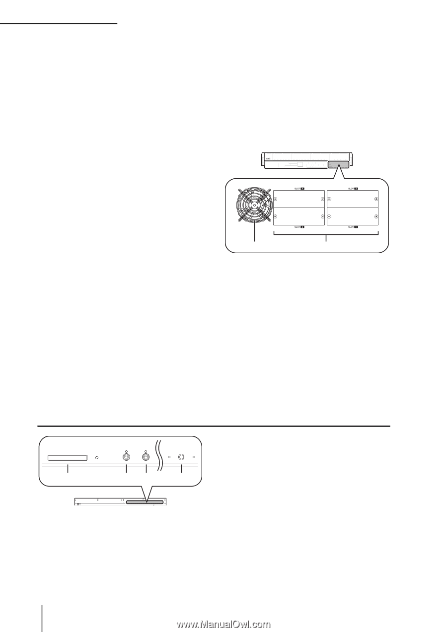
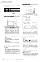
2 Top, front, and rear panels R RS422 REMOTE connector This is a D-sub 9-pin female connector for remotely controlling an external device that supports the RS422 protocol. S HA REMOTE connector This is a D-sub 9-pin male connector for remotely controlling an external head amp device (e.g., Yamaha AD8HR or AD824) that supports a special protocol. T WORD CLOCK IN connector This is a BNC connector for supplying a word clock from an external device to the PM5D. U 75Ω ON/OFF switch This switch terminates the word clock connection. Normally you will leave this ON. If a device made by another manufacturer is connected and word clock cannot be received correctly, try turning this OFF. V WORD CLOCK OUT connector This is a BNC connector for supplying a word clock from the PM5D to an external device. W MIDI IN/THRU/OUT connectors These connectors are used to transmit and receive MIDI messages to and from external MIDI devices. The MIDI IN connector receives messages from an external device, and the MIDI OUT connector transmits messages from the PM5D. Messages received at the MIDI IN connector are retransmitted without change from the MIDI THRU connector. X 2TR OUT DIGITAL (2 track out digital) jacks 1-3 These jacks digitally output the signals of the STEREO A/B channels. Two types are provided; AES/EBU (XLR-3-32) jacks (1/2) which output AES/EBU format signals, and a COAXIAL (RCA phono) jack (3) which outputs consumer format signals (IEC60958). Y 2TR IN DIGITAL (2 track in digital) jacks 1-3 These jacks input digital audio from external devices such as CD players. Two types are provided; AES/EBU (XLR-3-31) jacks (1/2) which receive AES/EBU format signals, and a COAXIAL (RCA phono) jack (3) which receives consumer format signals (IEC60958). Front panel MEMORY CARD 1 6 5 4 3 21 MOUSE 6 5 4 3 21 KEYBOARD 23 PHONES 4 MEMORY CARD MOUSE KEYBOARD PHONES Z CASCADE OUT connector This is a D-sub half-pitch 68-pin female connector that can be connected to another PM5D for transmission/ reception of control signals and transmission of audio signals. a CASCADE IN connector This is a D-sub half-pitch 68-pin female connector that can be connected to another PM5D for transmission/ reception of control signals and reception of audio signals. b c b Fan grille This is an output grille for the fan that cools the interior of the console (two locations). Be careful not to obstruct the fan exhaust. c SLOT 1-4 These slots allow separately sold mini-YGDAI I/O cards to be installed to expand the input/output ports. A MEMORY CARD slot A memory card inserted in this slot can be used to save/load scene memories or library data. You can use PCMCIA Type II flash ATA cards, or CompactFlash cards inserted into a PC card adaptor. B MOUSE connector A PS/2 mouse can be connected to this connector and used to perform operations in the display. C KEYBOARD connector A PS/2 keyboard can be connected to this connector and used to input text or perform operations in the display. D PHONES (Headphone) jack This headphone jack lets you monitor the MONITOR OUT or CUE signals. 18 PM5D/PM5D-RH Owner's Manual Operating section
-
 1
1 -
2
-
3
-
4
-
5
-
6
-
7
-
8
-
9
-
10
-
11
-
12
-
 13
13 -
 14
14 -
 15
15 -
 16
16 -
 17
17 -
 18
18 -
 19
19 -
 20
20 -
 21
21 -
 22
22 -
 23
23 -
24
-
25
-
26
-
27
-
28
-
29
-
30
-
31
-
32
-
33
-
34
-
35
-
36
-
37
-
38
-
39
-
40
-
41
-
42
-
43
-
44
-
45
-
46
-
47
-
48
-
49
-
50
-
51
-
52
-
53
-
54
-
55
-
56
-
57
-
58
-
59
-
60
-
61
-
62
-
63
-
64
-
65
-
66
-
67
-
68
-
69
-
70
-
71
-
72
-
73
-
74
-
75
-
76
-
77
-
78
-
79
-
80
-
81
-
82
-
83
-
84
-
85
-
86
-
87
-
88
-
89
-
90
-
91
-
92
-
93
-
94
-
95
-
96
-
97
-
98
-
99
-
100
-
101
-
102
-
103
-
104
-
105
-
106
-
107
-
108
-
109
-
110
-
111
-
112
-
113
-
114
-
115
-
116
-
117
-
118
-
119
-
120
-
121
-
122
-
123
-
124
-
125
-
126
-
127
-
128
-
129
-
130
-
131
-
132
-
133
-
134
-
135
-
136
-
137
-
138
-
139
-
140
-
141
-
142
-
143
-
144
-
145
-
146
-
147
-
148
-
149
-
150
-
151
-
152
-
153
-
154
-
155
-
156
-
157
-
158
-
159
-
160
-
161
-
162
-
163
-
164
-
165
-
166
-
167
-
168
-
169
-
170
-
171
-
172
-
173
-
174
-
175
-
176
-
177
-
178
-
179
-
180
-
181
-
182
-
183
-
184
-
185
-
186
-
187
-
188
-
189
-
190
-
191
-
192
-
193
-
194
-
195
-
196
-
197
-
198
-
199
-
200
-
201
-
202
-
203
-
204
-
205
-
206
-
207
-
208
-
209
-
210
-
211
-
212
-
213
-
214
-
215
-
216
-
217
-
218
-
219
-
220
-
221
-
222
-
223
-
224
-
225
-
226
-
227
-
228
-
229
-
230
-
231
-
232
-
233
-
234
-
235
-
236
-
237
-
238
-
239
-
240
-
241
-
242
-
243
-
244
-
245
-
246
-
247
-
248
-
249
-
250
-
251
-
252
-
253
-
254
-
255
-
256
-
257
-
258
-
259
-
260
-
261
-
262
-
263
-
264
-
265
-
266
-
267
-
268
-
269
-
270
-
271
-
272
-
273
-
274
-
275
-
276
-
277
-
278
-
279
-
280
-
281
-
282
-
283
-
284
-
285
-
286
-
287
-
288
-
289
-
290
-
291
-
292
-
293
-
294
-
295
-
296
-
297
-
298
-
299
-
300
-
301
-
302
-
303
-
304
-
305
-
306
-
307
-
308
-
309
-
310
-
311
-
312
-
313
-
314
-
315
-
316
-
317
-
318
-
319
-
320
-
321
-
322
-
323
-
324
-
325
-
326
-
327
-
328
-
329
-
330
-
331
-
332
-
333
-
334
-
335
-
336
-
337
-
338
-
339
-
340
-
341
-
342
-
343
-
344
-
345
-
346
-
347
-
348
-
349
-
350
-
351
-
352
-
353
-
354
-
355
-
356
-
357
-
358
-
359
-
360
-
361
-
362
-
363
-
364
-
365
-
366
-
367
 |
 |