Yamaha PM5D Owner's Manual - Page 282
FIX ASSIGN VIEW screen, Input channel, Bus assignments, TO ST To stereo, DIRECT, Output port
 |
View all Yamaha PM5D manuals
Add to My Manuals
Save this manual to your list of manuals |
Page 282 highlights
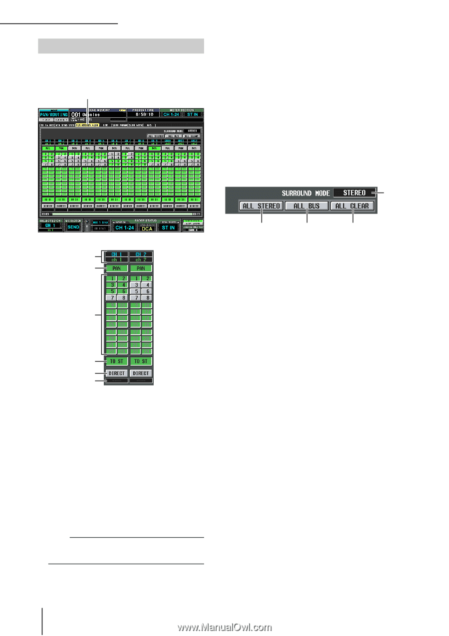
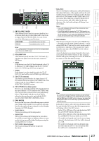
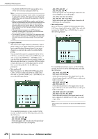
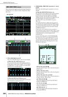
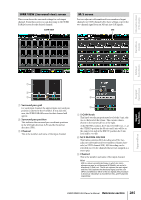
PAN/ROUTING function FIX ASSIGN VIEW screen This screen lists the signals sent from the input channels to the buses and direct outputs. You can also set or cancel these assignments from within this screen. FIX ASSIGN VIEW D TO ST (To stereo) If this button is on, the corresponding input channel is assigned to the STEREO bus. This is linked with the TO ST button of the CH to MIX screen (PAN/ROUTING function). E DIRECT If this button is on, the signal of the corresponding input channel will be sent to the output port selected as the direct output. This is linked with the DIRECT OUT ON/OFF button in the INSERT/DIRECT OUT POINT screen (IN PATCH function). F Output port This area indicates the output port that is patched in the DIRECT OUT PATCH screen (INPUT PATCH function) to the direct output of this input channel J 1 2 3 4 5 6 A Input channel This area indicates the number and name of the input channel you are editing. B PAN If this button is on, the input channel's TO STEREO PAN knob setting will also apply to the signal sent to FIXED-type MIX buses. This is linked with the FOLLOW PAN FIXED button of the CH to MIX screen (PAN/ROUTING function). C Bus assignments These buttons assign the corresponding input channel to FIXED-type MIX buses. These are linked with the SEND ON/OFF buttons of the CH to MIX screen (PAN/ROUTING function). For VARI-type MIX buses, the buttons are grayed-out and inoperable. Note If a surround mode other than STEREO is selected, the buttons for MIX buses used as surround buses will be named by their surround channel (e.g., L, C, R) rather than by number. 7 8 9 G ALL STEREO Clicking this button enables the assignment of all input channels to the STEREO bus. H ALL BUS Clicking this button enables the assignment of all input channels to FIXED-type MIX buses. I ALL CLEAR Clicking this button cancels all assignments in the FIX ASSIGN VIEW screen. J SURROUND MODE This indicates the currently selected surround mode. 282 PM5D/PM5D-RH Owner's Manual Reference section
-
 1
1 -
2
-
3
-
4
-
5
-
6
-
7
-
8
-
9
-
10
-
11
-
12
-
13
-
14
-
15
-
16
-
17
-
18
-
19
-
20
-
21
-
22
-
23
-
24
-
25
-
26
-
27
-
28
-
29
-
30
-
31
-
32
-
33
-
34
-
35
-
36
-
37
-
38
-
39
-
40
-
41
-
42
-
43
-
44
-
45
-
46
-
47
-
48
-
49
-
50
-
51
-
52
-
53
-
54
-
55
-
56
-
57
-
58
-
59
-
60
-
61
-
62
-
63
-
64
-
65
-
66
-
67
-
68
-
69
-
70
-
71
-
72
-
73
-
74
-
75
-
76
-
77
-
78
-
79
-
80
-
81
-
82
-
83
-
84
-
85
-
86
-
87
-
88
-
89
-
90
-
91
-
92
-
93
-
94
-
95
-
96
-
97
-
98
-
99
-
100
-
101
-
102
-
103
-
104
-
105
-
106
-
107
-
108
-
109
-
110
-
111
-
112
-
113
-
114
-
115
-
116
-
117
-
118
-
119
-
120
-
121
-
122
-
123
-
124
-
125
-
126
-
127
-
128
-
129
-
130
-
131
-
132
-
133
-
134
-
135
-
136
-
137
-
138
-
139
-
140
-
141
-
142
-
143
-
144
-
145
-
146
-
147
-
148
-
149
-
150
-
151
-
152
-
153
-
154
-
155
-
156
-
157
-
158
-
159
-
160
-
161
-
162
-
163
-
164
-
165
-
166
-
167
-
168
-
169
-
170
-
171
-
172
-
173
-
174
-
175
-
176
-
177
-
178
-
179
-
180
-
181
-
182
-
183
-
184
-
185
-
186
-
187
-
188
-
189
-
190
-
191
-
192
-
193
-
194
-
195
-
196
-
197
-
198
-
199
-
200
-
201
-
202
-
203
-
204
-
205
-
206
-
207
-
208
-
209
-
210
-
211
-
212
-
213
-
214
-
215
-
216
-
217
-
218
-
219
-
220
-
221
-
222
-
223
-
224
-
225
-
226
-
227
-
228
-
229
-
230
-
231
-
232
-
233
-
234
-
235
-
236
-
237
-
238
-
239
-
240
-
241
-
242
-
243
-
244
-
245
-
246
-
247
-
248
-
249
-
250
-
251
-
252
-
253
-
254
-
255
-
256
-
257
-
258
-
259
-
260
-
261
-
262
-
263
-
264
-
265
-
266
-
267
-
268
-
269
-
270
-
271
-
272
-
273
-
274
-
275
-
276
-
 277
277 -
 278
278 -
 279
279 -
 280
280 -
 281
281 -
 282
282 -
 283
283 -
 284
284 -
 285
285 -
 286
286 -
 287
287 -
288
-
289
-
290
-
291
-
292
-
293
-
294
-
295
-
296
-
297
-
298
-
299
-
300
-
301
-
302
-
303
-
304
-
305
-
306
-
307
-
308
-
309
-
310
-
311
-
312
-
313
-
314
-
315
-
316
-
317
-
318
-
319
-
320
-
321
-
322
-
323
-
324
-
325
-
326
-
327
-
328
-
329
-
330
-
331
-
332
-
333
-
334
-
335
-
336
-
337
-
338
-
339
-
340
-
341
-
342
-
343
-
344
-
345
-
346
-
347
-
348
-
349
-
350
-
351
-
352
-
353
-
354
-
355
-
356
-
357
-
358
-
359
-
360
-
361
-
362
-
363
-
364
-
365
-
366
-
367
 |
 |