Yamaha PM5D Owner's Manual - Page 42
Sending a signal from an input channel to the STEREO bus, REO A [ON] key and STEREO B [ON] key
 |
View all Yamaha PM5D manuals
Add to My Manuals
Save this manual to your list of manuals |
Page 42 highlights
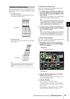
5 Input channel operations Sending a signal from an input channel to the STEREO bus Here's how to use the INPUT channel strip or ST IN/FX RTN channel strip to send an input channel signal to the STEREO bus. The explanation here uses the example of an input channel, but the procedure is essentially identical when using a ST IN channel or FX RTN channel. 1 Make sure that an input source is correctly assigned to the input channel, and that the head amp gain is set appropriately. 2 Make sure that the appropriate CH [ON] key is turned on in the INPUT channel strip, and press the [SEL] key for that channel to make it light. The [SEL] keys are used to select the channel you want to control. 4 Raise the corresponding fader of the INPUT channel strip. The level of the input signal is shown by the level meter located at the right of the CH [ON] key. 5 Turn on the [PAN] key in the ENCODER MODE section. 6 Use the encoder in the INPUT channel strip to adjust the pan of the input channel. Note If you are sending the signal from a ST IN channel / FX RTN channel to the STEREO bus, you can repeatedly press the [SEL] key to switch between L/R channels, and make pan settings for each channel. 7 In the STEREO A/B channel strip, turn the STEREO A [ON] key and STEREO B [ON] key on (LED lit). STEREO A [ON] key STEREO B [ON] key [SEL] key CH [ON] key Level meter 3 In the SELECTED CHANNEL section, press the [TO STEREO] key to make it light. In the SELECTED CHANNEL section you can make detailed parameters settings for the channel currently selected by its [SEL] key. (For details on the SELECTED CHANNEL section ➥ p.57.) When you turn on the [TO STEREO] key, the signal sent from that input channel to the STEREO bus will be turned on. At this time, the [TO ST] LED of the INPUT channel strip will light. [TO STEREO] key STEREO A fader STEREO B fader 8 In the STEREO A/B channel strip, raise the [STEREO A]/[STEREO B] faders. The signal sent to the stereo bus will be routed through the STEREO A/B channels and output from the STEREO OUT A/B jacks. STEREO [PAN] encoder 42 PM5D/PM5D-RH Owner's Manual Operating section
-
 1
1 -
2
-
3
-
4
-
5
-
6
-
7
-
8
-
9
-
10
-
11
-
12
-
13
-
14
-
15
-
16
-
17
-
18
-
19
-
20
-
21
-
22
-
23
-
24
-
25
-
26
-
27
-
28
-
29
-
30
-
31
-
32
-
33
-
34
-
35
-
36
-
 37
37 -
 38
38 -
 39
39 -
 40
40 -
 41
41 -
 42
42 -
 43
43 -
 44
44 -
 45
45 -
 46
46 -
 47
47 -
48
-
49
-
50
-
51
-
52
-
53
-
54
-
55
-
56
-
57
-
58
-
59
-
60
-
61
-
62
-
63
-
64
-
65
-
66
-
67
-
68
-
69
-
70
-
71
-
72
-
73
-
74
-
75
-
76
-
77
-
78
-
79
-
80
-
81
-
82
-
83
-
84
-
85
-
86
-
87
-
88
-
89
-
90
-
91
-
92
-
93
-
94
-
95
-
96
-
97
-
98
-
99
-
100
-
101
-
102
-
103
-
104
-
105
-
106
-
107
-
108
-
109
-
110
-
111
-
112
-
113
-
114
-
115
-
116
-
117
-
118
-
119
-
120
-
121
-
122
-
123
-
124
-
125
-
126
-
127
-
128
-
129
-
130
-
131
-
132
-
133
-
134
-
135
-
136
-
137
-
138
-
139
-
140
-
141
-
142
-
143
-
144
-
145
-
146
-
147
-
148
-
149
-
150
-
151
-
152
-
153
-
154
-
155
-
156
-
157
-
158
-
159
-
160
-
161
-
162
-
163
-
164
-
165
-
166
-
167
-
168
-
169
-
170
-
171
-
172
-
173
-
174
-
175
-
176
-
177
-
178
-
179
-
180
-
181
-
182
-
183
-
184
-
185
-
186
-
187
-
188
-
189
-
190
-
191
-
192
-
193
-
194
-
195
-
196
-
197
-
198
-
199
-
200
-
201
-
202
-
203
-
204
-
205
-
206
-
207
-
208
-
209
-
210
-
211
-
212
-
213
-
214
-
215
-
216
-
217
-
218
-
219
-
220
-
221
-
222
-
223
-
224
-
225
-
226
-
227
-
228
-
229
-
230
-
231
-
232
-
233
-
234
-
235
-
236
-
237
-
238
-
239
-
240
-
241
-
242
-
243
-
244
-
245
-
246
-
247
-
248
-
249
-
250
-
251
-
252
-
253
-
254
-
255
-
256
-
257
-
258
-
259
-
260
-
261
-
262
-
263
-
264
-
265
-
266
-
267
-
268
-
269
-
270
-
271
-
272
-
273
-
274
-
275
-
276
-
277
-
278
-
279
-
280
-
281
-
282
-
283
-
284
-
285
-
286
-
287
-
288
-
289
-
290
-
291
-
292
-
293
-
294
-
295
-
296
-
297
-
298
-
299
-
300
-
301
-
302
-
303
-
304
-
305
-
306
-
307
-
308
-
309
-
310
-
311
-
312
-
313
-
314
-
315
-
316
-
317
-
318
-
319
-
320
-
321
-
322
-
323
-
324
-
325
-
326
-
327
-
328
-
329
-
330
-
331
-
332
-
333
-
334
-
335
-
336
-
337
-
338
-
339
-
340
-
341
-
342
-
343
-
344
-
345
-
346
-
347
-
348
-
349
-
350
-
351
-
352
-
353
-
354
-
355
-
356
-
357
-
358
-
359
-
360
-
361
-
362
-
363
-
364
-
365
-
366
-
367
 |
 |
