Yamaha PM5D Owner's Manual - Page 144
Selecting the buses used for cascade connection, connection
 |
View all Yamaha PM5D manuals
Add to My Manuals
Save this manual to your list of manuals |
Page 144 highlights
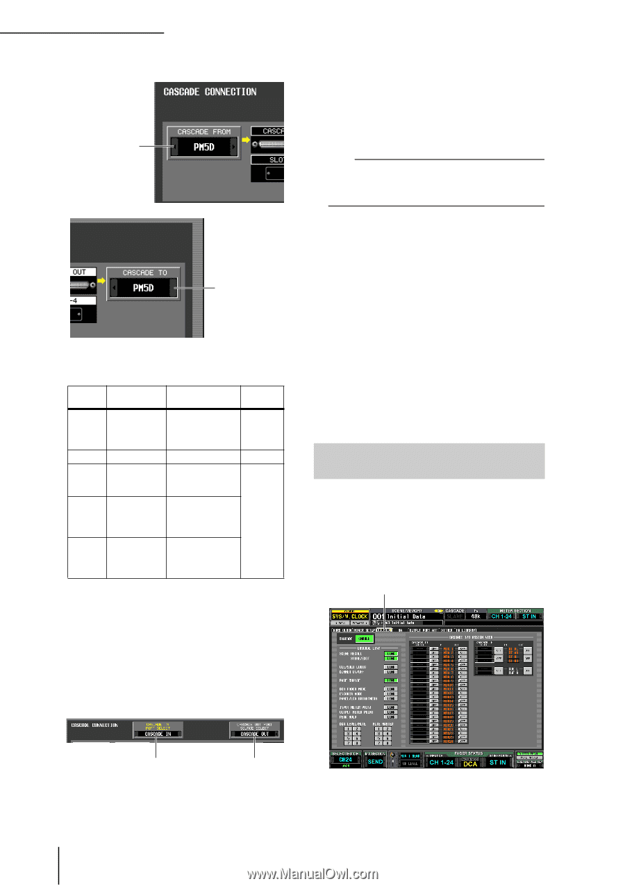
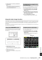
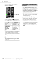
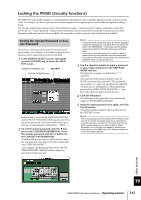
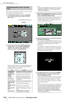
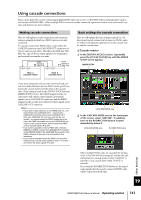
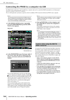
19 Other functions 3 Select "PM5D" in the CASCADE FROM field and in the CASCADE TO field. CASCADE FROM field through which audio signals will be transmitted to and received from the cascade-connected external device. If "PM5D" or "DM2000/02R96" are selected as the other cascade-connected device, only "CASCADE IN" can be selected for the CASCADE IN PORT SELECT field. In the CASCADE OUT PORT SOURCE SELECT field, you can choose from the output channels of slots 1-4 as well as "CASCADE OUT" (➥ p.203). Hint If you choose a setting other than "CASCADE OUT" in the CASCADE OUT PORT SOURCE SELECT field, the same signal will be output from both the specified slot/channel and from the CASCADE OUT connector. CASCADE TO field In the CASCADE FROM field, select one of the following as the type of the external device that is sending signals to the PM5D via the cascade connection. Display Source device Selectable cas- Parameter cade input port linkage - PM5D Cascade disabled another PM5D CASCADE IN, SLOT 4, SLOT 3/4, SLOT1-4 [CH1-8], SLOT 1-4 [CH9-16] CASCADE IN Not possible Possible*1 DM2000 /02R96 YAMAHA DM2000 or 02R96 CASCADE IN MIXER [30BUS] A mixer other than the above (maximum 30 bus) SLOT 3/4, SLOT 1-4 [CH1-8], SLOT 1-4 [CH9-16] Not possible MIXER [16BUS] A mixer other than the above (maximum 16 bus) SLOT 4 *1. Linked parameters are specified in the CASCADE screen. In the CASCADE TO field, select either "PM5D" or "---" (transmission disabled) as the external device to which the signal will be sent from the PM5D via the cascade connection. 4 Make sure that "CASCADE IN" is selected for the CASCADE IN PORT SELECT field, and "CASCADE OUT" is selected for the CASCADE OUT PORT SOURCE SELECT field. ❏ Cascade slave 1 In the DISPLAY ACCESS section, repeatedly press the [SYS/W.CLOCK] key to access the MIXER SETUP screen. 2 In the CASCADE MODE area at the lower part of the screen, select "SLAVE". In addition, turn on the BI-DIRECTION button located immediately below it. 3 Select "PM5D" in the CASCADE FROM field and in the CASCADE TO field. 4 Make sure that "CASCADE IN" is selected in the CASCADE IN PORT SELECT field, and "CASCADE OUT" is selected in the CASCADE OUT PORT SOURCE SELECT field. Selecting the buses used for cascade connection Here we will explain how to select the buses used for the cascade connection, specify the items that will be linked, and enable the cascade connection. Perform the following steps on both the cascade master and cascade slave units. 1 In the DISPLAY ACCESS section, repeatedly press the [SYS/W.CLOCK] key until the CASCADE screen shown below appears. CASCADE CASCADE IN PORT SELECT field CASCADE OUT PORT SOURCE SELECT field The CASCADE IN PORT SELECT and CASCADE OUT PORT SOURCE SELECT fields select the ports In this combination you can enable/disable buses used for transmission/reception in the cascade connection, and select the operations that will be linked when multiple PM5D units are cascade-connected. 144 PM5D/PM5D-RH Owner's Manual Operating section
-
 1
1 -
2
-
3
-
4
-
5
-
6
-
7
-
8
-
9
-
10
-
11
-
12
-
13
-
14
-
15
-
16
-
17
-
18
-
19
-
20
-
21
-
22
-
23
-
24
-
25
-
26
-
27
-
28
-
29
-
30
-
31
-
32
-
33
-
34
-
35
-
36
-
37
-
38
-
39
-
40
-
41
-
42
-
43
-
44
-
45
-
46
-
47
-
48
-
49
-
50
-
51
-
52
-
53
-
54
-
55
-
56
-
57
-
58
-
59
-
60
-
61
-
62
-
63
-
64
-
65
-
66
-
67
-
68
-
69
-
70
-
71
-
72
-
73
-
74
-
75
-
76
-
77
-
78
-
79
-
80
-
81
-
82
-
83
-
84
-
85
-
86
-
87
-
88
-
89
-
90
-
91
-
92
-
93
-
94
-
95
-
96
-
97
-
98
-
99
-
100
-
101
-
102
-
103
-
104
-
105
-
106
-
107
-
108
-
109
-
110
-
111
-
112
-
113
-
114
-
115
-
116
-
117
-
118
-
119
-
120
-
121
-
122
-
123
-
124
-
125
-
126
-
127
-
128
-
129
-
130
-
131
-
132
-
133
-
134
-
135
-
136
-
137
-
138
-
 139
139 -
 140
140 -
 141
141 -
 142
142 -
 143
143 -
 144
144 -
 145
145 -
 146
146 -
 147
147 -
 148
148 -
 149
149 -
150
-
151
-
152
-
153
-
154
-
155
-
156
-
157
-
158
-
159
-
160
-
161
-
162
-
163
-
164
-
165
-
166
-
167
-
168
-
169
-
170
-
171
-
172
-
173
-
174
-
175
-
176
-
177
-
178
-
179
-
180
-
181
-
182
-
183
-
184
-
185
-
186
-
187
-
188
-
189
-
190
-
191
-
192
-
193
-
194
-
195
-
196
-
197
-
198
-
199
-
200
-
201
-
202
-
203
-
204
-
205
-
206
-
207
-
208
-
209
-
210
-
211
-
212
-
213
-
214
-
215
-
216
-
217
-
218
-
219
-
220
-
221
-
222
-
223
-
224
-
225
-
226
-
227
-
228
-
229
-
230
-
231
-
232
-
233
-
234
-
235
-
236
-
237
-
238
-
239
-
240
-
241
-
242
-
243
-
244
-
245
-
246
-
247
-
248
-
249
-
250
-
251
-
252
-
253
-
254
-
255
-
256
-
257
-
258
-
259
-
260
-
261
-
262
-
263
-
264
-
265
-
266
-
267
-
268
-
269
-
270
-
271
-
272
-
273
-
274
-
275
-
276
-
277
-
278
-
279
-
280
-
281
-
282
-
283
-
284
-
285
-
286
-
287
-
288
-
289
-
290
-
291
-
292
-
293
-
294
-
295
-
296
-
297
-
298
-
299
-
300
-
301
-
302
-
303
-
304
-
305
-
306
-
307
-
308
-
309
-
310
-
311
-
312
-
313
-
314
-
315
-
316
-
317
-
318
-
319
-
320
-
321
-
322
-
323
-
324
-
325
-
326
-
327
-
328
-
329
-
330
-
331
-
332
-
333
-
334
-
335
-
336
-
337
-
338
-
339
-
340
-
341
-
342
-
343
-
344
-
345
-
346
-
347
-
348
-
349
-
350
-
351
-
352
-
353
-
354
-
355
-
356
-
357
-
358
-
359
-
360
-
361
-
362
-
363
-
364
-
365
-
366
-
367
 |
 |