Yamaha PM5D Owner's Manual - Page 287
SIGNAL FLOW screen, SURROUND Surround pan
 |
View all Yamaha PM5D manuals
Add to My Manuals
Save this manual to your list of manuals |
Page 287 highlights
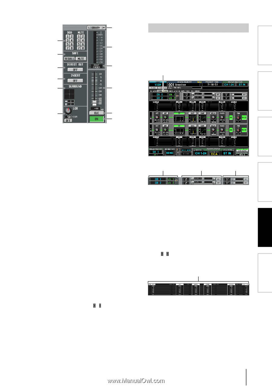
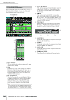
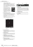
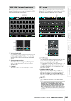
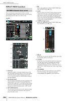
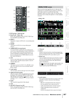
Information shown in the display P SIGNAL FLOW screen This screen shows the signal flow for two adjacent odd- J numbered/even-numbered input channels or ST IN chan- Q nels. In this screen you can also edit some of the K parameters, and access other screens. You can also deter- mine the location within the signal flow at which clipping L R occurred. SIGNAL FLOW M N S Function menu Global functions Output functions Input functions O T U J DCA group / Mute group K Recall safe / Mute safe Refer to the explanation of the OUTPUT VIEW function CH VIEW screen (➥ p.246). L DIRECT Turns direct output on/off for the corresponding input channel. M INSERT Turns insert on/off for the corresponding input channel. N SURROUND (Surround pan) If surround mode is enabled, the surround pan position of the corresponding input channel is indicated by the O symbol in the surround pan grid and also as a front/rear/left/right coordinate position. If you click the surround pan grid, the SURR PARAM screen for that channel will appear. O LCR Here you can switch LCR mode on/off, and adjust CSR (the level of the CENTER channel relative to the L/R channels) (➥ p.242). P LIBRARY This button accesses the INPUT CH LIBRARY screen (➥ p.289), where you can store/recall input channel library settings. Q Level meter This level meter indicates the input level of the channel. R Signal detection point This is the point at which the signal level shown in the level meter (S) is detected (PRE ATT, PRE GATE, PRE FADER, POST FADER, or POST ON). You can edit this setting by clicking the / buttons at the left and right. S Fader This controls the input level of the channel. T CUE U ON/OFF (Channel on/off) Refer to the explanation of the OUTPUT VIEW function CH VIEW screen (➥ p.247). 1 2 3 A Channel B Insert Except for the fact that this screen depicts input channels, the contents are the same as the OUTPUT VIEW function SIGNAL FLOW screen. Refer to p.247. C Direct out This area displays information about the direct output of the two selected channels (the signal output position, the port patched to direct out, and the direct output on/off status). Here you can also select the signal output position (use the / buttons at left and right), and switch direct output on/off (use the ON/OFF button). 4 D Level meters These meters indicate the levels at various points in the signal flow. Levels are detected at the following locations. • PRE ATT (immediately before the attenuator) • EQ (immediately before and after the EQ) • GATE (immediately before and after the gate) • COMP (immediately before and after the compressor) • FADER (immediately before and after the fader) PM5D/PM5D-RH Owner's Manual Reference section 287 Appendices
-
 1
1 -
2
-
3
-
4
-
5
-
6
-
7
-
8
-
9
-
10
-
11
-
12
-
13
-
14
-
15
-
16
-
17
-
18
-
19
-
20
-
21
-
22
-
23
-
24
-
25
-
26
-
27
-
28
-
29
-
30
-
31
-
32
-
33
-
34
-
35
-
36
-
37
-
38
-
39
-
40
-
41
-
42
-
43
-
44
-
45
-
46
-
47
-
48
-
49
-
50
-
51
-
52
-
53
-
54
-
55
-
56
-
57
-
58
-
59
-
60
-
61
-
62
-
63
-
64
-
65
-
66
-
67
-
68
-
69
-
70
-
71
-
72
-
73
-
74
-
75
-
76
-
77
-
78
-
79
-
80
-
81
-
82
-
83
-
84
-
85
-
86
-
87
-
88
-
89
-
90
-
91
-
92
-
93
-
94
-
95
-
96
-
97
-
98
-
99
-
100
-
101
-
102
-
103
-
104
-
105
-
106
-
107
-
108
-
109
-
110
-
111
-
112
-
113
-
114
-
115
-
116
-
117
-
118
-
119
-
120
-
121
-
122
-
123
-
124
-
125
-
126
-
127
-
128
-
129
-
130
-
131
-
132
-
133
-
134
-
135
-
136
-
137
-
138
-
139
-
140
-
141
-
142
-
143
-
144
-
145
-
146
-
147
-
148
-
149
-
150
-
151
-
152
-
153
-
154
-
155
-
156
-
157
-
158
-
159
-
160
-
161
-
162
-
163
-
164
-
165
-
166
-
167
-
168
-
169
-
170
-
171
-
172
-
173
-
174
-
175
-
176
-
177
-
178
-
179
-
180
-
181
-
182
-
183
-
184
-
185
-
186
-
187
-
188
-
189
-
190
-
191
-
192
-
193
-
194
-
195
-
196
-
197
-
198
-
199
-
200
-
201
-
202
-
203
-
204
-
205
-
206
-
207
-
208
-
209
-
210
-
211
-
212
-
213
-
214
-
215
-
216
-
217
-
218
-
219
-
220
-
221
-
222
-
223
-
224
-
225
-
226
-
227
-
228
-
229
-
230
-
231
-
232
-
233
-
234
-
235
-
236
-
237
-
238
-
239
-
240
-
241
-
242
-
243
-
244
-
245
-
246
-
247
-
248
-
249
-
250
-
251
-
252
-
253
-
254
-
255
-
256
-
257
-
258
-
259
-
260
-
261
-
262
-
263
-
264
-
265
-
266
-
267
-
268
-
269
-
270
-
271
-
272
-
273
-
274
-
275
-
276
-
277
-
278
-
279
-
280
-
281
-
 282
282 -
 283
283 -
 284
284 -
 285
285 -
 286
286 -
 287
287 -
 288
288 -
 289
289 -
 290
290 -
 291
291 -
 292
292 -
293
-
294
-
295
-
296
-
297
-
298
-
299
-
300
-
301
-
302
-
303
-
304
-
305
-
306
-
307
-
308
-
309
-
310
-
311
-
312
-
313
-
314
-
315
-
316
-
317
-
318
-
319
-
320
-
321
-
322
-
323
-
324
-
325
-
326
-
327
-
328
-
329
-
330
-
331
-
332
-
333
-
334
-
335
-
336
-
337
-
338
-
339
-
340
-
341
-
342
-
343
-
344
-
345
-
346
-
347
-
348
-
349
-
350
-
351
-
352
-
353
-
354
-
355
-
356
-
357
-
358
-
359
-
360
-
361
-
362
-
363
-
364
-
365
-
366
-
367
 |
 |