Yamaha PM5D Owner's Manual - Page 222
INSERT POINT screen
 |
View all Yamaha PM5D manuals
Add to My Manuals
Save this manual to your list of manuals |
Page 222 highlights
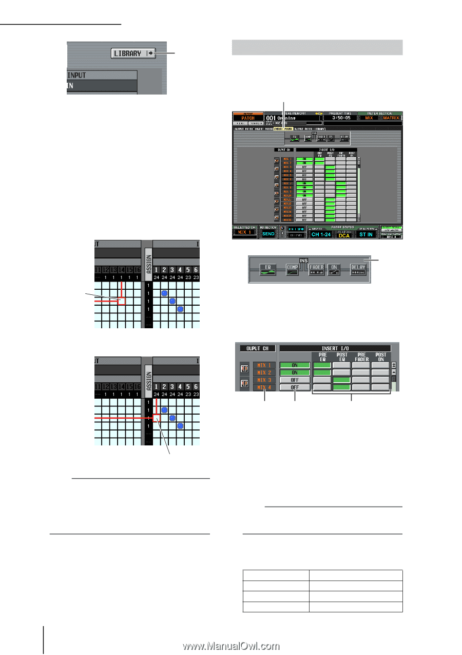
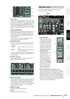
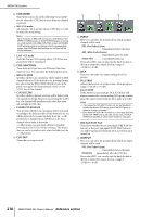
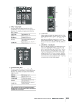
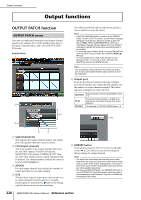
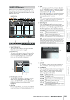
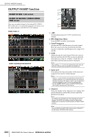
OUTPUT PATCH function 9 I LIBRARY button This button accesses the OUTPUT PATCH LIBRARY screen (➥ p.223), where you can store/recall patch library settings for output channels. ❏ Using the [SHIFT] key + CURSOR to move the cursor When operating from the panel, you can move the cursor from the right side of the screen to the left side (or vice versa) by holding down the [SHIFT] key and using the CURSOR [√]/[®] keys. To quickly move the cursor in or out of the grid, hold down the [SHIFT] key and press the CURSOR keys. INSERT POINT screen In this screen you can select the position at which the insert-in/out of each output channel will be patched. Here you can also switch insert-in on/off. INSERT POINT 1 Cursor [SHIFT] key + CURSOR [®] key ➠ A Insert view When you move the cursor to the insert I/O point (4), the insert point for that output channel will be shown graphically. Cursor will move Note To enable an insert-in assigned to an output channel in this screen, you must turn on the ON/OFF button for the corresponding output channel in the INSERT POINT screen (OUTPUT PATCH function). (➥ p.222) However, the insertout is always on, regardless of the state of the ON/OFF button. An exception to the above is that if you insert GEQ, its insert-in will automatically be on. 2 3 4 B OUTPUT CH (Output channel) This is the number of the output channel you are editing. Two paired channels are indicated by a heart symbol shown at the left; settings 3-4 will be linked for these channels. You can click this symbol to enable/ disable pairing. C ON/OFF (Insert on/off) This button switches insert on/off for each channel. This is linked for paired channels. Note Be aware that if you turn on this button when either insert-in or insert-out are unpatched, the signal will no longer be output from the corresponding output channel. D INSERT I/O (Insert I/O point) Here you can select one of the following as the insertin/out location for each output channel. PRE EQ POST EQ PRE FADER POST ON Immediately before the EQ Immediately after the EQ Immediately before the fader Immediately after the [ON] key 222 PM5D/PM5D-RH Owner's Manual Reference section
-
 1
1 -
2
-
3
-
4
-
5
-
6
-
7
-
8
-
9
-
10
-
11
-
12
-
13
-
14
-
15
-
16
-
17
-
18
-
19
-
20
-
21
-
22
-
23
-
24
-
25
-
26
-
27
-
28
-
29
-
30
-
31
-
32
-
33
-
34
-
35
-
36
-
37
-
38
-
39
-
40
-
41
-
42
-
43
-
44
-
45
-
46
-
47
-
48
-
49
-
50
-
51
-
52
-
53
-
54
-
55
-
56
-
57
-
58
-
59
-
60
-
61
-
62
-
63
-
64
-
65
-
66
-
67
-
68
-
69
-
70
-
71
-
72
-
73
-
74
-
75
-
76
-
77
-
78
-
79
-
80
-
81
-
82
-
83
-
84
-
85
-
86
-
87
-
88
-
89
-
90
-
91
-
92
-
93
-
94
-
95
-
96
-
97
-
98
-
99
-
100
-
101
-
102
-
103
-
104
-
105
-
106
-
107
-
108
-
109
-
110
-
111
-
112
-
113
-
114
-
115
-
116
-
117
-
118
-
119
-
120
-
121
-
122
-
123
-
124
-
125
-
126
-
127
-
128
-
129
-
130
-
131
-
132
-
133
-
134
-
135
-
136
-
137
-
138
-
139
-
140
-
141
-
142
-
143
-
144
-
145
-
146
-
147
-
148
-
149
-
150
-
151
-
152
-
153
-
154
-
155
-
156
-
157
-
158
-
159
-
160
-
161
-
162
-
163
-
164
-
165
-
166
-
167
-
168
-
169
-
170
-
171
-
172
-
173
-
174
-
175
-
176
-
177
-
178
-
179
-
180
-
181
-
182
-
183
-
184
-
185
-
186
-
187
-
188
-
189
-
190
-
191
-
192
-
193
-
194
-
195
-
196
-
197
-
198
-
199
-
200
-
201
-
202
-
203
-
204
-
205
-
206
-
207
-
208
-
209
-
210
-
211
-
212
-
213
-
214
-
215
-
216
-
 217
217 -
 218
218 -
 219
219 -
 220
220 -
 221
221 -
 222
222 -
 223
223 -
 224
224 -
 225
225 -
 226
226 -
 227
227 -
228
-
229
-
230
-
231
-
232
-
233
-
234
-
235
-
236
-
237
-
238
-
239
-
240
-
241
-
242
-
243
-
244
-
245
-
246
-
247
-
248
-
249
-
250
-
251
-
252
-
253
-
254
-
255
-
256
-
257
-
258
-
259
-
260
-
261
-
262
-
263
-
264
-
265
-
266
-
267
-
268
-
269
-
270
-
271
-
272
-
273
-
274
-
275
-
276
-
277
-
278
-
279
-
280
-
281
-
282
-
283
-
284
-
285
-
286
-
287
-
288
-
289
-
290
-
291
-
292
-
293
-
294
-
295
-
296
-
297
-
298
-
299
-
300
-
301
-
302
-
303
-
304
-
305
-
306
-
307
-
308
-
309
-
310
-
311
-
312
-
313
-
314
-
315
-
316
-
317
-
318
-
319
-
320
-
321
-
322
-
323
-
324
-
325
-
326
-
327
-
328
-
329
-
330
-
331
-
332
-
333
-
334
-
335
-
336
-
337
-
338
-
339
-
340
-
341
-
342
-
343
-
344
-
345
-
346
-
347
-
348
-
349
-
350
-
351
-
352
-
353
-
354
-
355
-
356
-
357
-
358
-
359
-
360
-
361
-
362
-
363
-
364
-
365
-
366
-
367
 |
 |