Yamaha PM5D Owner's Manual - Page 200
MIXER SETUP screen, OUTPUT FORMAT Output signal format
 |
View all Yamaha PM5D manuals
Add to My Manuals
Save this manual to your list of manuals |
Page 200 highlights
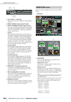
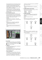
SYS/W.CLOCK function 34 5 67 8 C Slot number / Card type This area shows the type of digital I/O card installed in slots 1-4. D INPUT FORMAT (Input signal format) E OUTPUT FORMAT (Output signal format) Select one of the following as the method by which signals will be exchanged with a digital I/O card installed in the slot when the PM5D is operating at a high sampling rate (88.2/96 kHz). • SINGLE This setting allows transmission/reception of the normal number of channels when existing equipment that operates at 44.1/48 kHz is connected. The sampling rate will be converted for each channel of the digital I/ O card, and transmitted/received at half the sampling frequency (44.1/48 kHz) of the PM5D. (This setting can be selected only for slots in which a digital I/O card that does not support 96 kHz is installed.) • DOUBLE SPEED This setting allows high sampling rate audio signals to be transmitted/received without change when equipment that operates at a high sampling rate (88.2/96 kHz) is connected. (This setting can be connected only for slots in which a digital I/O card that supports 96 kHz is installed.) • DOUBLE CHANNEL This setting allows high sampling rate (88.2/96 kHz) audio signals to be handled when existing equipment that operates at 44.1/48 kHz is connected. Two channels of signals at half the PM5D's sampling frequency (44.1/48 kHz) are transmitted/received together as a high sampling rate monaural signal. (The number of usable channels will be half.) F FREQUENCY (Sampling frequency) This indicates the sampling frequency of the signal being input to each channel of the digital I/O card, in sets of two channels. G SRC (Sampling Rate Converter) This button switches the Sampling Rate Converter on/ off, in sets of two channels. This is available only for slots in which a digital I/O card with a built-in sampling rate converter is installed. H EMPHASIS STATUS This indicates whether emphasis is applied to the input signal, in sets of two channels. This is available only for slots in which a digital I/O card is installed. MIXER SETUP screen Here you can make settings that apply to the entire PM5D system. MIXER SETUP 1 2 A PAIR MODE Select one of the following two methods by which input channels will be paired. • HORIZONTAL PAIR If this button is on, input channels of adjacent numbers (1/2, 3/4 ...) will be paired. • VERTICAL PAIR If this button is on, input channels of different layers that share the same fader (1/25, 2/26 ...) will be paired. This setting lets you use the faders of the INPUT channel strip to control up to 24 pairs (48 channels). Hint The graphic below the buttons will change according to the pair mode you select. When you switch from horizontal pair mode to vertical pair mode, new numbers will be assigned to the input channels as follows. Channel 1 → no change Channel 2 → Channel 25 Channel 3 → Channel 2 Channel 4 → Channel 26 : Channel 47 → Channel 24 Channel 48 → no change 200 PM5D/PM5D-RH Owner's Manual Reference section
-
 1
1 -
2
-
3
-
4
-
5
-
6
-
7
-
8
-
9
-
10
-
11
-
12
-
13
-
14
-
15
-
16
-
17
-
18
-
19
-
20
-
21
-
22
-
23
-
24
-
25
-
26
-
27
-
28
-
29
-
30
-
31
-
32
-
33
-
34
-
35
-
36
-
37
-
38
-
39
-
40
-
41
-
42
-
43
-
44
-
45
-
46
-
47
-
48
-
49
-
50
-
51
-
52
-
53
-
54
-
55
-
56
-
57
-
58
-
59
-
60
-
61
-
62
-
63
-
64
-
65
-
66
-
67
-
68
-
69
-
70
-
71
-
72
-
73
-
74
-
75
-
76
-
77
-
78
-
79
-
80
-
81
-
82
-
83
-
84
-
85
-
86
-
87
-
88
-
89
-
90
-
91
-
92
-
93
-
94
-
95
-
96
-
97
-
98
-
99
-
100
-
101
-
102
-
103
-
104
-
105
-
106
-
107
-
108
-
109
-
110
-
111
-
112
-
113
-
114
-
115
-
116
-
117
-
118
-
119
-
120
-
121
-
122
-
123
-
124
-
125
-
126
-
127
-
128
-
129
-
130
-
131
-
132
-
133
-
134
-
135
-
136
-
137
-
138
-
139
-
140
-
141
-
142
-
143
-
144
-
145
-
146
-
147
-
148
-
149
-
150
-
151
-
152
-
153
-
154
-
155
-
156
-
157
-
158
-
159
-
160
-
161
-
162
-
163
-
164
-
165
-
166
-
167
-
168
-
169
-
170
-
171
-
172
-
173
-
174
-
175
-
176
-
177
-
178
-
179
-
180
-
181
-
182
-
183
-
184
-
185
-
186
-
187
-
188
-
189
-
190
-
191
-
192
-
193
-
194
-
 195
195 -
 196
196 -
 197
197 -
 198
198 -
 199
199 -
 200
200 -
 201
201 -
 202
202 -
 203
203 -
 204
204 -
 205
205 -
206
-
207
-
208
-
209
-
210
-
211
-
212
-
213
-
214
-
215
-
216
-
217
-
218
-
219
-
220
-
221
-
222
-
223
-
224
-
225
-
226
-
227
-
228
-
229
-
230
-
231
-
232
-
233
-
234
-
235
-
236
-
237
-
238
-
239
-
240
-
241
-
242
-
243
-
244
-
245
-
246
-
247
-
248
-
249
-
250
-
251
-
252
-
253
-
254
-
255
-
256
-
257
-
258
-
259
-
260
-
261
-
262
-
263
-
264
-
265
-
266
-
267
-
268
-
269
-
270
-
271
-
272
-
273
-
274
-
275
-
276
-
277
-
278
-
279
-
280
-
281
-
282
-
283
-
284
-
285
-
286
-
287
-
288
-
289
-
290
-
291
-
292
-
293
-
294
-
295
-
296
-
297
-
298
-
299
-
300
-
301
-
302
-
303
-
304
-
305
-
306
-
307
-
308
-
309
-
310
-
311
-
312
-
313
-
314
-
315
-
316
-
317
-
318
-
319
-
320
-
321
-
322
-
323
-
324
-
325
-
326
-
327
-
328
-
329
-
330
-
331
-
332
-
333
-
334
-
335
-
336
-
337
-
338
-
339
-
340
-
341
-
342
-
343
-
344
-
345
-
346
-
347
-
348
-
349
-
350
-
351
-
352
-
353
-
354
-
355
-
356
-
357
-
358
-
359
-
360
-
361
-
362
-
363
-
364
-
365
-
366
-
367
 |
 |
