Yamaha RX-A830 RX-A830 Owners Manual - Page 10
Rear panel, REMOTE IN/OUT jacks
 |
View all Yamaha RX-A830 manuals
Add to My Manuals
Save this manual to your list of manuals |
Page 10 highlights
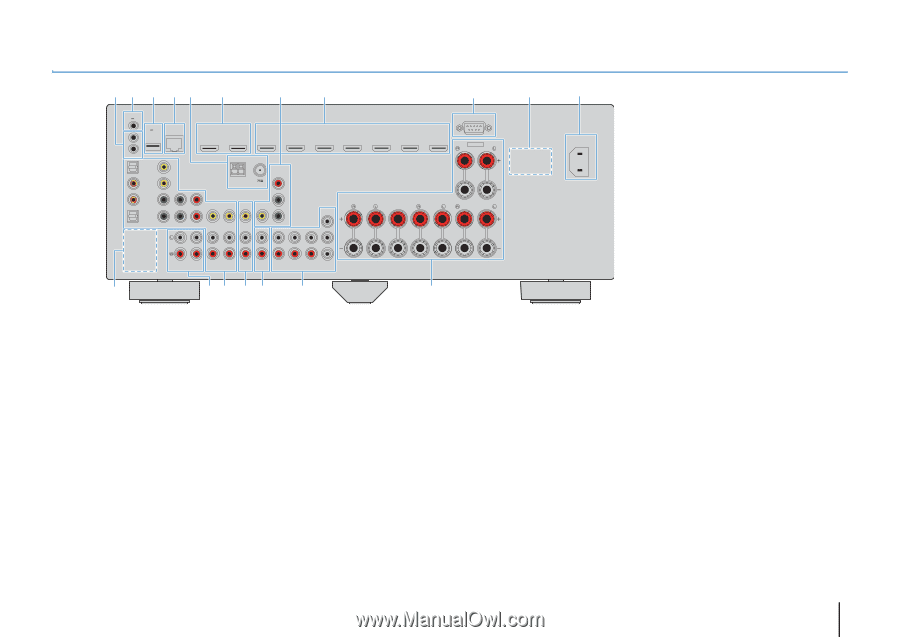
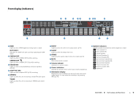
Rear panel 12 3 45 6 7 8 9 TRIGGER OUT 12V 0.1A DC OUT NETWORK 5V 0.5A (NET) IN OUT REMOTE OPTICAL (TV) AV4 COAXIAL VIDEO AV3 Y PB PR AV2 OPTICAL AV 1 COMPONENT VIDEO HDMI OUT 1 2 ARC HDMI 1 (BD/DVD) HDMI 2 HDMI 3 VIDEO AM FM (RADIO) ANTENNA COMPONENT VIDEO PR PB VIDEO Y MONITOR OUT CENTER SINGLE 1 HDMI 4 HDMI 5 HDMI 6 HDMI 7 FRONT SPEAKERS CENTER SURROUND 2 AUDIO 1 AUDIO 2 AV 5 AV 6 ZONE 2 FRONT SURROUND SUR. BACK SUBWOOFER AV OUT ZONE OUT PRE OUT RS-232C EXTRA SP ZONE2/F.PRESENCE SURROUND BACK/BI-AMP SINGLE B CD EF G H : A (U.S.A. model) AC IN * The area around the video/audio output jacks is marked in white on the actual product to prevent improper connections. 1 REMOTE IN/OUT jacks For connecting to an infrared signal receiver/emitter that allows you to operate the unit and other devices from another room (p.71). 2 TRIGGER OUT jack For connecting to a device that supports the trigger function (p.33). 3 DC OUT jack For connecting to an optional accessory. 4 NETWORK jack For connecting to a network (p.31). 5 ANTENNA jacks For connecting to FM and AM antennas (p.31). 6 HDMI OUT 1-2 jacks For connecting to HDMI-compatible TVs and outputting video/audio signals (p.21). When using ARC, TV audio signal can also be input through the HDMI OUT 1 jack. 7 MONITOR OUT jacks COMPONENT VIDEO jacks For connecting to a TV that supports component video and outputting video signals (p.25). VIDEO jack For connecting to a TV that supports composite video and outputting video signals (p.25). 8 HDMI 1-7 jacks For connecting to HDMI-compatible playback devices and inputting video/audio signals (p.26). 9 RS-232C terminal This is a control expansion terminal for custom installation. Consult your dealer for details. 0 VOLTAGE SELECTOR (General model only) Selects the switch position according to your local voltage (p.33). A AC IN jack For connecting the supplied power cable (p.33). B PHONO jacks (Except for U.S.A. and Canada models) For connecting to a turntable (p.29). C AUDIO 1-2 jacks For connecting to audio playback devices and inputting audio signals (p.29). D AV 1-6 jacks For connecting to video/audio playback devices and inputting video/audio signals (p.26). E AV OUT jacks For outputting video/audio to a recording device (such as a VCR) (p.32). F ZONE2 OUT jacks For connecting to the external amplifier used in Zone2 and for outputting audio (p.71). G PRE OUT jacks For connecting to a subwoofer with built-in amplifier or to an external power amplifier (p.32). H SPEAKERS terminals For connecting to speakers (p.17). FEATURES ➤ Part names and functions En 10
-
 1
1 -
2
-
3
-
4
-
 5
5 -
 6
6 -
 7
7 -
 8
8 -
 9
9 -
 10
10 -
 11
11 -
 12
12 -
 13
13 -
 14
14 -
 15
15 -
16
-
17
-
18
-
19
-
20
-
21
-
22
-
23
-
24
-
25
-
26
-
27
-
28
-
29
-
30
-
31
-
32
-
33
-
34
-
35
-
36
-
37
-
38
-
39
-
40
-
41
-
42
-
43
-
44
-
45
-
46
-
47
-
48
-
49
-
50
-
51
-
52
-
53
-
54
-
55
-
56
-
57
-
58
-
59
-
60
-
61
-
62
-
63
-
64
-
65
-
66
-
67
-
68
-
69
-
70
-
71
-
72
-
73
-
74
-
75
-
76
-
77
-
78
-
79
-
80
-
81
-
82
-
83
-
84
-
85
-
86
-
87
-
88
-
89
-
90
-
91
-
92
-
93
-
94
-
95
-
96
-
97
-
98
-
99
-
100
-
101
-
102
-
103
-
104
-
105
-
106
-
107
-
108
-
109
-
110
-
111
-
112
-
113
-
114
-
115
-
116
-
117
-
118
-
119
-
120
-
121
-
122
-
123
-
124
-
125
-
126
-
127
-
128
-
129
-
130
-
131
-
132
-
133
-
134
-
135
-
136
 |
 |