Yamaha RX-A830 RX-A830 Owners Manual - Page 25
Connection Method 4 TV without HDMI input jacks, Connecting another TV or a projector
 |
View all Yamaha RX-A830 manuals
Add to My Manuals
Save this manual to your list of manuals |
Page 25 highlights
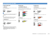
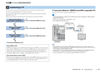
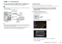
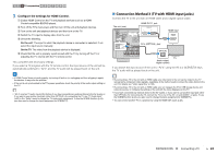
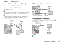
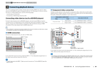
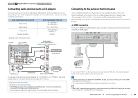
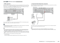
1 2 3 TV connection 4 5 6 7 8 9 10 ■ Connection Method 4 (TV without HDMI input jacks) When connecting any video device to the AV 1-2 (COMPONENT VIDEO) jacks of the unit, connect the TV to the MONITOR OUT (COMPONENT VIDEO) jacks. When connecting any video device to the AV 3-6 (VIDEO) jacks or the front VIDEO jack of the unit, connect the TV to the MONITOR OUT (VIDEO) jack. If you select "AV 4" as the input source by pressing AV 4 or SCENE(TV), the TV audio will be played back on the unit. • If you connect your TV to the unit with a cable other than HDMI, video input to the unit via HDMI cannot be output to the TV. • Operations with TV screen are available only when your TV is connected to the unit via HDMI. • If you have connected any external device to the AV 4 jacks or if you want to use another input jack (other than OPTICAL) for connecting the TV, connect the TV to one of the AV 1-6 and AUDIO 1-2 jacks. To use the SCENE function (p.44), you also need to change the input assignment for SCENE(TV). ❑ COMPONENT VIDEO connection (with a component video cable) MONITOR OUT (COMPONENT VIDEO) jacks COMPONENT VIDEO The unit (rear) PR PR TRIGGER OUT 12V 0.1A DC OUT NETWORK 5V 0.5A (NET) IN OUT HDMI OUT 1 2 ARC HDMI 1 (BD/DVD) PB H Y PB Y REMOTE OPTICAL (TV) AV4 COAXIAL VIDEO AV3 Y PB PR OPTICAL AV2 OPTICAL AV 1 (TV) AV4 COMPONENT VIDEO VIDEO O TOR OUT AM FM (RADIO) ANTENNA COMPONENT VIDEO PR PB VIDEO Y MONITOR OUT O AUDIO 1 AUDIO 2 AV 5 AV 6 ZONE 2 FRONT SU AV OUT ZONE OUT Video input (component video) COMPONENT VIDEO PR PR PB PB Y Y OPTICAL AV 4 (OPTICAL) jack TV Audio output (digital optical) ❑ VIDEO (composite video) connection (with a video pin cable) The unit (rear) MONITOR OUT (VIDEO) jack TRIGGER OUT 12V 0.1A DC OUT NETWORK 5V 0.5A (NET) IN OUT HDMI OUT 1 2 ARC HDMI 1 H (BD/DVD) VIDEO REMOTE OPTICAL (TV) AV4 COAXIAL AV3 VIDEO AM FM V COMPONENT VIDEO MONITOR (RADIO) ANTENNA PR Y PB PR OPTICAL AV2 OPTICAL (TV) AV4 AV 1 COMPONENT VIDEO VIDEO O PB VIDEO Y MONITOR OUT AUDIO 1 AUDIO 2 AV 5 AV 6 ZONE 2 FRONT SU AV OUT ZONE OUT AV 4 (OPTICAL) jack Video input (composite video) VIDEO V OPTICAL O Audio output TV (digital optical) ■ Connecting another TV or a projector The unit has two HDMI output jacks. If you connect another TV or a projector to the unit with an HDMI cable, you can switch the TV (or projector) to be used for watching videos with the remote control (p.43). HDMI OUT 2 jack The unit (rear) HDMI OUT 1 2 ARC TRIGGER OUT 12V 0.1A DC OUT NETWORK 5V 0.5A (NET) IN OUT REMOTE OPTICAL (TV) AV4 COAXIAL VIDEO AV3 Y PB PR AV2 OPTICAL HDMI OUT 1 2 ARC AM H (BD FM (RADIO) ANTENNA VIDEO VIDE AV 1 COMPONENT VIDEO MO HDMI TV HDMI HDMI input HDMI AUDIO 1 AUDIO 2 AV 5 AV 6 ZONE AV OUT ZONE O TV (already connected) Projector • HDMI Control is not available on the HDMI OUT 2 jack. PREPARATIONS ➤ Connecting a TV En 25
-
 1
1 -
2
-
3
-
4
-
5
-
6
-
7
-
8
-
9
-
10
-
11
-
12
-
13
-
14
-
15
-
16
-
17
-
18
-
19
-
 20
20 -
 21
21 -
 22
22 -
 23
23 -
 24
24 -
 25
25 -
 26
26 -
 27
27 -
 28
28 -
 29
29 -
 30
30 -
31
-
32
-
33
-
34
-
35
-
36
-
37
-
38
-
39
-
40
-
41
-
42
-
43
-
44
-
45
-
46
-
47
-
48
-
49
-
50
-
51
-
52
-
53
-
54
-
55
-
56
-
57
-
58
-
59
-
60
-
61
-
62
-
63
-
64
-
65
-
66
-
67
-
68
-
69
-
70
-
71
-
72
-
73
-
74
-
75
-
76
-
77
-
78
-
79
-
80
-
81
-
82
-
83
-
84
-
85
-
86
-
87
-
88
-
89
-
90
-
91
-
92
-
93
-
94
-
95
-
96
-
97
-
98
-
99
-
100
-
101
-
102
-
103
-
104
-
105
-
106
-
107
-
108
-
109
-
110
-
111
-
112
-
113
-
114
-
115
-
116
-
117
-
118
-
119
-
120
-
121
-
122
-
123
-
124
-
125
-
126
-
127
-
128
-
129
-
130
-
131
-
132
-
133
-
134
-
135
-
136
 |
 |
