ZyXEL GS-1548 User Guide - Page 31
Rear Panel, Power Connector - reset
 |
View all ZyXEL GS-1548 manuals
Add to My Manuals
Save this manual to your list of manuals |
Page 31 highlights
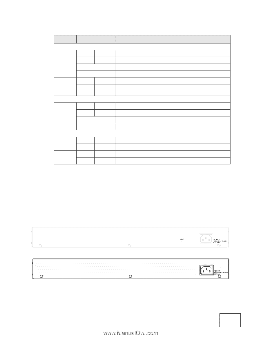
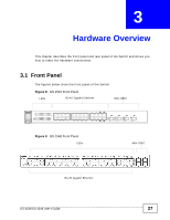
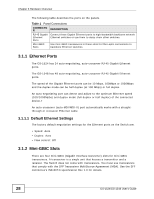
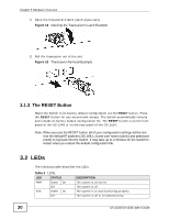
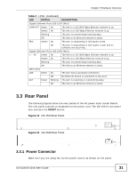
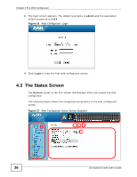
Chapter 3 Hardware Overview Table 2 LEDs (continued) LED STATUS DESCRIPTION Gigabit Ethernet Ports (GS-1524 ONLY) LINK/ACT Green On The link to a 10/1000 Mbps Ethernet network is up. Amber On The link to a 100 Mbps Ethernet network is up. Blinking The port is transmitting/receiving data. Off The link to an Ethernet network is down. FDX Amber On The port is negotiating in full-duplex mode. Off The port is negotiating in half-duplex mode and no collisions are occurring. Gigabit Ethernet Ports (GS-1548 ONLY) 1 ~ 48 Green On The link to a 10/1000 Mbps Ethernet network is up. Amber On The link to a 100 Mbps Ethernet network is up. Blinking The port is transmitting/receiving data. Off The link to an Ethernet network is down. GBIC Slots LNK Green On The port has a successful connection. Off No Ethernet device is connected to this port. ACT Green Blinking The port is receiving or transmitting data. Off The link to an Ethernet network is down. 3.3 Rear Panel The following figures show the rear panels of the AC power input model Switch. The rear panel contains a receptacle for the power cord. The GS-1524's rear panel also contains the RESET button. Figure 14 GS-1524 Rear Panel Figure 15 GS-1548 Rear Panel 3.3.1 Power Connector Make sure you are using the correct power source as shown on the panel. GS-1524/GS-1548 User's Guide 31
-
 1
1 -
2
-
3
-
4
-
5
-
6
-
7
-
8
-
9
-
10
-
11
-
12
-
13
-
14
-
15
-
16
-
17
-
18
-
19
-
20
-
21
-
22
-
23
-
24
-
25
-
 26
26 -
 27
27 -
 28
28 -
 29
29 -
 30
30 -
 31
31 -
 32
32 -
 33
33 -
 34
34 -
 35
35 -
 36
36 -
37
-
38
-
39
-
40
-
41
-
42
-
43
-
44
-
45
-
46
-
47
-
48
-
49
-
50
-
51
-
52
-
53
-
54
-
55
-
56
-
57
-
58
-
59
-
60
-
61
-
62
-
63
-
64
-
65
-
66
-
67
-
68
-
69
-
70
-
71
-
72
-
73
-
74
-
75
-
76
-
77
-
78
-
79
-
80
-
81
-
82
-
83
-
84
-
85
-
86
-
87
-
88
-
89
-
90
-
91
-
92
-
93
-
94
-
95
-
96
-
97
-
98
-
99
-
100
-
101
-
102
-
103
-
104
-
105
-
106
-
107
-
108
-
109
-
110
-
111
-
112
-
113
-
114
-
115
-
116
-
117
-
118
-
119
-
120
-
121
-
122
-
123
-
124
-
125
-
126
-
127
-
128
-
129
-
130
-
131
-
132
-
133
-
134
-
135
-
136
-
137
-
138
-
139
-
140
-
141
-
142
-
143
-
144
-
145
-
146
-
147
-
148
-
149
-
150
-
151
-
152
-
153
-
154
-
155
-
156
-
157
-
158
-
159
-
160
-
161
-
162
-
163
-
164
-
165
-
166
-
167
-
168
-
169
-
170
 |
 |