ZyXEL GS1910-24 User Guide - Page 22
LEDs, Hardware Overview, GS1910/XGS1910 Series User's Guide
 |
View all ZyXEL GS1910-24 manuals
Add to My Manuals
Save this manual to your list of manuals |
Page 22 highlights
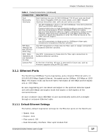
Chapter 3 Hardware Overview 3.3 LEDs The following table describes the LEDs. Table 2 LEDs LED COLOR PoE (GS191048HP only) Green STATUS On Off STACK (XGS191 0-24 and XGS1910 -48 only) Green Amber On On Blinking PWR SYS Green Green Off On Off Blinking On Off ALM Red On Off 10/100/1000 Mbps RJ-45 Ports LNK/ACT Green Blinking Amber On Blinking On Off PoE Green On (GS1910- 24HP and GS1910- Amber On 48HP only) Off SFP Slots DESCRIPTION Each Ethernet port's LED is changed to act as a PoE LED by using the LED MODE button on the front panel. Each Ethernet port's LED is changed back to act as a LNK/ACT LED by using the LED MODE button on the front panel. The Switch is acting as the master in stacking. The Switch is acting as the backup master device in stacking. The Switch is acting as a slave member in stacking and is being selected by the master in its web configurator stack screen. The Switch is not working in stacking mode. The system is turned on. The system is off. The system is rebooting and performing self-diagnostic tests. The system is on and functioning properly. The power is off or the system is not ready/ malfunctioning. There is a hardware failure. The system is functioning normally. The system is transmitting/receiving to/from a 10/1000 Mbps Ethernet network. The link to a 10/1000 Mbps Ethernet network is up. The system is transmitting/receiving to/from a 100 Mbps Ethernet network. The link to a 100 Mbps Ethernet network is up. The link to an Ethernet network is down. Power supplied to all PoE Ethernet ports meets the IEEE 802.3at standard. Power supplied to all PoE Ethernet ports meets the IEEE 802.3af standard. There is no power supplied. 22 GS1910/XGS1910 Series User's Guide
-
 1
1 -
2
-
3
-
4
-
5
-
6
-
7
-
8
-
9
-
10
-
11
-
12
-
13
-
14
-
15
-
16
-
 17
17 -
 18
18 -
 19
19 -
 20
20 -
 21
21 -
 22
22 -
 23
23 -
 24
24 -
 25
25 -
 26
26 -
 27
27 -
28
-
29
-
30
-
31
-
32
-
33
-
34
-
35
-
36
-
37
-
38
-
39
-
40
-
41
-
42
-
43
-
44
-
45
-
46
-
47
-
48
-
49
-
50
-
51
-
52
-
53
-
54
-
55
-
56
-
57
-
58
-
59
-
60
-
61
-
62
-
63
-
64
-
65
-
66
-
67
-
68
-
69
-
70
-
71
-
72
-
73
-
74
-
75
-
76
 |
 |
