ZyXEL GS1910-24 User Guide - Page 38
How to Create a VLAN - vlan configuration
 |
View all ZyXEL GS1910-24 manuals
Add to My Manuals
Save this manual to your list of manuals |
Page 38 highlights
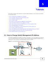
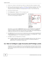
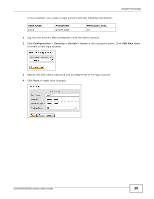
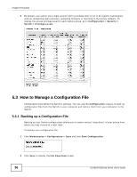
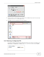
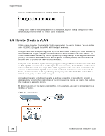
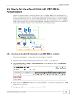
Chapter 5 Tutorials After the upload is successful, the following screen displays. "config" is the name of the configuration file on the Switch, so your backup configuration file is automatically renamed when you restore using this screen. 5.4 How to Create a VLAN VLANs confine broadcast frames to the VLAN group in which the port(s) belongs. You can do this using IEEE 802.1Q tagged static VLAN with fixed port members. A tagged VLAN uses an explicit tag (VLAN ID) in the MAC header to identify the VLAN membership of a frame across bridges - they are not confined to the switch on which they were created. The VLANs can be created statically by hand or dynamically through Multiple VLAN Registration Protocol (MVRP). The VLAN ID associates a frame with a specific VLAN and provides the information that switches need to process the frame across the network. Each port on the Switch is capable of passing tagged or untagged frames. To forward a frame from an 802.1Q VLAN-aware switch to an 802.1Q VLAN-unaware switch, the Switch first decides where to forward the frame and then strips off the VLAN tag. To forward a frame from an 802.1Q VLANunaware switch to an 802.1Q VLAN-aware switch, the Switch first decides where to forward the frame, and then inserts a VLAN tag reflecting the ingress port's default VID. The default PVID is VLAN 1 for all ports, but this can be changed. A broadcast frame (or a multicast frame for a multicast group that is known by the system) is duplicated only on ports that are members of the VID (except the ingress port itself), thus confining the broadcast to a specific domain. By default, all ports on the Switch are in VLAN 1. In this example, you want to configure port 1 as a member of VLAN 2. Figure 28 VLAN Example 38 GS1910/XGS1910 Series User's Guide
-
 1
1 -
2
-
3
-
4
-
5
-
6
-
7
-
8
-
9
-
10
-
11
-
12
-
13
-
14
-
15
-
16
-
17
-
18
-
19
-
20
-
21
-
22
-
23
-
24
-
25
-
26
-
27
-
28
-
29
-
30
-
31
-
32
-
 33
33 -
 34
34 -
 35
35 -
 36
36 -
 37
37 -
 38
38 -
 39
39 -
 40
40 -
 41
41 -
 42
42 -
 43
43 -
44
-
45
-
46
-
47
-
48
-
49
-
50
-
51
-
52
-
53
-
54
-
55
-
56
-
57
-
58
-
59
-
60
-
61
-
62
-
63
-
64
-
65
-
66
-
67
-
68
-
69
-
70
-
71
-
72
-
73
-
74
-
75
-
76
 |
 |
