ZyXEL P-2024 User Guide - Page 29
Ports, 1.4.2 LEDs, 1.4.3 Console Port, Table 1 - dsp p
 |
View all ZyXEL P-2024 manuals
Add to My Manuals
Save this manual to your list of manuals |
Page 29 highlights
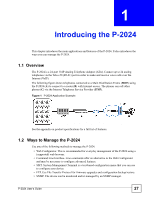
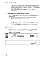
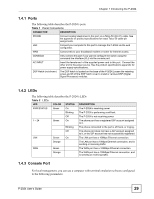
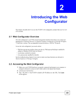
Chapter 1 Introducing the P-2024 1.4.1 Ports The following table describes the P-2024's ports. Table 1 Panel Connections CONNECTOR DESCRIPTION PHONE Connect analog telephones to this port via a Telco-50 (RJ-21) cable. See the appendix on product specifications for exact Telco-50 cable pin assignments. LAN Connect your computer to this port to manage the P-2024 via the web configurator. WAN Connect this to your broadband modem or router for Internet access. CONSOLE Only connect this port if you want to configure the switch using the command line interface (CLI) via the console port. AC INPUT Insert the female end of the supplied power cord to this port. Connect the other end to the power source. See the product specifications appendix for power supply specifications. DSP Hatch (not shown) The DSP hatch is located on the base of the P-2024.Loosen the retaining screw and lift off the DSP hatch cover to install or remove DSP (Digital Signal Processor) modules. 1.4.2 LEDs The following table describes the P-2024's LEDs Table 2 LEDs LED COLOR STATUS DESCRIPTION PWR/STATUS Green On The P-2024 is receiving power. Blinking The P-2024 is performing a self-test. Off The P-2024 is not receiving power. 1 ~ 24 Green On The phone port has a registered SIP account assigned to it. Blinking The phone connected to the port is off-hook, or ringing. Off The phone port does not have a SIP account assigned to it, or the SIP account has not successfully registered. LAN Green On The LAN port has a 10Mbps Ethernet connection. Orange The LAN port has a 10Mbps Ethernet connection, and is sending or receiving traffic. WAN Green The WAN port has a 100Mbps Ethernet connection. Orange The WAN port has a 100Mbps Ethernet connection, and is sending or receiving traffic. 1.4.3 Console Port For local management, you can use a computer with terminal emulation software configured to the following parameters: P-2024 User's Guide 29
-
 1
1 -
2
-
3
-
4
-
5
-
6
-
7
-
8
-
9
-
10
-
11
-
12
-
13
-
14
-
15
-
16
-
17
-
18
-
19
-
20
-
21
-
22
-
23
-
 24
24 -
 25
25 -
 26
26 -
 27
27 -
 28
28 -
 29
29 -
 30
30 -
 31
31 -
 32
32 -
 33
33 -
 34
34 -
35
-
36
-
37
-
38
-
39
-
40
-
41
-
42
-
43
-
44
-
45
-
46
-
47
-
48
-
49
-
50
-
51
-
52
-
53
-
54
-
55
-
56
-
57
-
58
-
59
-
60
-
61
-
62
-
63
-
64
-
65
-
66
-
67
-
68
-
69
-
70
-
71
-
72
-
73
-
74
-
75
-
76
-
77
-
78
-
79
-
80
-
81
-
82
-
83
-
84
-
85
-
86
-
87
-
88
-
89
-
90
-
91
-
92
-
93
-
94
-
95
-
96
-
97
-
98
-
99
-
100
-
101
-
102
-
103
-
104
-
105
-
106
-
107
-
108
-
109
-
110
-
111
-
112
-
113
-
114
-
115
-
116
-
117
-
118
-
119
-
120
-
121
-
122
-
123
-
124
-
125
-
126
-
127
-
128
-
129
-
130
-
131
-
132
-
133
-
134
-
135
-
136
-
137
-
138
-
139
-
140
-
141
-
142
-
143
-
144
-
145
-
146
-
147
-
148
-
149
-
150
-
151
-
152
-
153
-
154
-
155
-
156
-
157
-
158
-
159
-
160
-
161
-
162
-
163
-
164
-
165
-
166
-
167
-
168
-
169
-
170
-
171
-
172
-
173
-
174
-
175
-
176
-
177
-
178
-
179
-
180
-
181
-
182
-
183
-
184
-
185
-
186
-
187
-
188
-
189
-
190
-
191
-
192
-
193
-
194
-
195
-
196
-
197
-
198
-
199
-
200
-
201
-
202
-
203
-
204
-
205
-
206
 |
 |