ZyXEL P-2024 User Guide - Page 30
Digital Signal Processor Modules
 |
View all ZyXEL P-2024 manuals
Add to My Manuals
Save this manual to your list of manuals |
Page 30 highlights
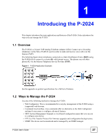
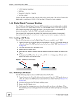
Chapter 1 Introducing the P-2024 • VT100 terminal emulation • 9600 bps • No parity, 8 data bits, 1 stop bit • No flow control Connect the male 9-pin end of the console cable to the console port of the switch. Connect the female end to a serial port (COM1, COM2 or other COM port) of your computer. 1.4.4 Digital Signal Processor Modules Your P-2024 uses Digital Signal Processor (DSP) modules to convert analog audio to digital signals, and vice versa. The P-2024 contains an onboard DSP module, and is also equipped with a single removable DSP module by default. You can also install a second module to increase the number of calls the P-2024 can handle simultaneously. The on-board DSP module and the default DSP module are each capable of processing 8 channels simultaneously. A normal one-to-one phone conversation occupies one channel. 1.4.4.1 Installing a DSP Module Take the following steps to install a Digital Signal Processor module in your P-2024. 1 Ensure the power is off and all cables are disconnected. Lay the P-2024 upside down on a flat, dry surface. The DSP hatch is located on the base of the P-2024 (see Section 1.4.1 on page 29). 2 Unscrew and remove the DSP hatch screw. 3 Remove the DSP hatch cover. 4 Insert the DSP module's contacts into the connector socket at an angle, as shown in the figure. 5 Gently press the DSP module downwards, until the two retaining arms click into place. Replace the hatch cover and the screw. Figure 3 Installing a DSP module 1.4.4.2 Removing a DSP Module Take the following steps to remove a DSP module from the P-2024. 1 Ensure the power is off and all cables are disconnected. Lay the P-2024 upside down on a flat, dry surface. The DSP hatch is located on the base of the P-2024 (see Section 1.4.1 on page 29). 2 Unscrew and remove the DSP hatch retaining screw. 3 Remove the DSP hatch cover. 4 Gently press the retaining arms away from the module, as shown in the figure. When both retaining arms are disengaged from the module, the module springs up to its angled position. 30 P-2024 User's Guide
-
 1
1 -
2
-
3
-
4
-
5
-
6
-
7
-
8
-
9
-
10
-
11
-
12
-
13
-
14
-
15
-
16
-
17
-
18
-
19
-
20
-
21
-
22
-
23
-
24
-
 25
25 -
 26
26 -
 27
27 -
 28
28 -
 29
29 -
 30
30 -
 31
31 -
 32
32 -
 33
33 -
 34
34 -
 35
35 -
36
-
37
-
38
-
39
-
40
-
41
-
42
-
43
-
44
-
45
-
46
-
47
-
48
-
49
-
50
-
51
-
52
-
53
-
54
-
55
-
56
-
57
-
58
-
59
-
60
-
61
-
62
-
63
-
64
-
65
-
66
-
67
-
68
-
69
-
70
-
71
-
72
-
73
-
74
-
75
-
76
-
77
-
78
-
79
-
80
-
81
-
82
-
83
-
84
-
85
-
86
-
87
-
88
-
89
-
90
-
91
-
92
-
93
-
94
-
95
-
96
-
97
-
98
-
99
-
100
-
101
-
102
-
103
-
104
-
105
-
106
-
107
-
108
-
109
-
110
-
111
-
112
-
113
-
114
-
115
-
116
-
117
-
118
-
119
-
120
-
121
-
122
-
123
-
124
-
125
-
126
-
127
-
128
-
129
-
130
-
131
-
132
-
133
-
134
-
135
-
136
-
137
-
138
-
139
-
140
-
141
-
142
-
143
-
144
-
145
-
146
-
147
-
148
-
149
-
150
-
151
-
152
-
153
-
154
-
155
-
156
-
157
-
158
-
159
-
160
-
161
-
162
-
163
-
164
-
165
-
166
-
167
-
168
-
169
-
170
-
171
-
172
-
173
-
174
-
175
-
176
-
177
-
178
-
179
-
180
-
181
-
182
-
183
-
184
-
185
-
186
-
187
-
188
-
189
-
190
-
191
-
192
-
193
-
194
-
195
-
196
-
197
-
198
-
199
-
200
-
201
-
202
-
203
-
204
-
205
-
206
 |
 |
