Brother International HL-720 Service Manual - Page 113
Reset Circuit, Fig. 2.10, CDCC I/O, II-11
 |
View all Brother International HL-720 manuals
Add to My Manuals
Save this manual to your list of manuals |
Page 113 highlights
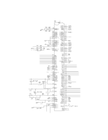
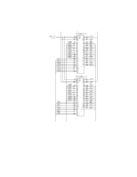
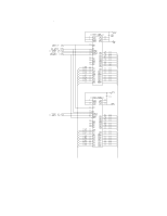
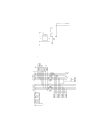
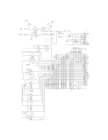
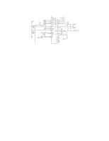
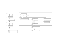
1.3.8 Reset Circuit The reset IC is PST591DMT. The reset voltage is 4.2V (typ.) and the LOW period of reset is 50 ms (typ). Fig. 2.10 1.3.9 CDCC I/O Fig. 2.11 shows the CDCC interface circuit. Fig. 2.11 II-11
-
 1
1 -
2
-
3
-
4
-
5
-
6
-
7
-
8
-
9
-
10
-
11
-
12
-
13
-
14
-
15
-
16
-
17
-
18
-
19
-
20
-
21
-
22
-
23
-
24
-
25
-
26
-
27
-
28
-
29
-
30
-
31
-
32
-
33
-
34
-
35
-
36
-
37
-
38
-
39
-
40
-
41
-
42
-
43
-
44
-
45
-
46
-
47
-
48
-
49
-
50
-
51
-
52
-
53
-
54
-
55
-
56
-
57
-
58
-
59
-
60
-
61
-
62
-
63
-
64
-
65
-
66
-
67
-
68
-
69
-
70
-
71
-
72
-
73
-
74
-
75
-
76
-
77
-
78
-
79
-
80
-
81
-
82
-
83
-
84
-
85
-
86
-
87
-
88
-
89
-
90
-
91
-
92
-
93
-
94
-
95
-
96
-
97
-
98
-
99
-
100
-
101
-
102
-
103
-
104
-
105
-
106
-
107
-
 108
108 -
 109
109 -
 110
110 -
 111
111 -
 112
112 -
 113
113 -
 114
114 -
 115
115 -
 116
116 -
 117
117 -
 118
118 -
119
-
120
-
121
-
122
-
123
-
124
-
125
-
126
-
127
-
128
-
129
-
130
-
131
-
132
-
133
-
134
-
135
-
136
-
137
-
138
-
139
-
140
-
141
-
142
-
143
-
144
-
145
-
146
-
147
-
148
-
149
-
150
-
151
-
152
-
153
-
154
 |
 |

II-11
1.3.8
Reset Circuit
The reset IC is PST591DMT. The reset voltage is 4.2V (typ.) and the LOW period of
reset is 50 ms (typ).
Fig. 2.10
1.3.9
CDCC I/O
Fig. 2.11 shows the CDCC interface circuit.
Fig. 2.11