Brother International HL-720 Service Manual - Page 55
Scanner Unit, Fig. 3.6, Main PCB Assy
 |
View all Brother International HL-720 manuals
Add to My Manuals
Save this manual to your list of manuals |
Page 55 highlights
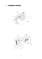
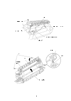
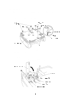
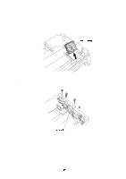
3.5 Scanner Unit (1) Remove the three screws. (2) Lift out the scanner unit. (3) Disconnect the three connectors of the scanner unit from the panel sensor PCB. (4) Remove the screw and disassemble the Toner sensor PCB from the Scanner unit. Fig. 3.6 NOTE: Never touch the inside of the scanner unit or the mirror when disassembling or reassembling. If there is any garbage or dust on the mirror, blow it off. 3.6 Main PCB Assy (1) Remove three screws securing the main PCB holder on the back side of the printer. (2) Grasp the hooks at left and right and draw out the main PCB assy. Fig. 3.7
-
 1
1 -
2
-
3
-
4
-
5
-
6
-
7
-
8
-
9
-
10
-
11
-
12
-
13
-
14
-
15
-
16
-
17
-
18
-
19
-
20
-
21
-
22
-
23
-
24
-
25
-
26
-
27
-
28
-
29
-
30
-
31
-
32
-
33
-
34
-
35
-
36
-
37
-
38
-
39
-
40
-
41
-
42
-
43
-
44
-
45
-
46
-
47
-
48
-
49
-
 50
50 -
 51
51 -
 52
52 -
 53
53 -
 54
54 -
 55
55 -
 56
56 -
 57
57 -
 58
58 -
 59
59 -
 60
60 -
61
-
62
-
63
-
64
-
65
-
66
-
67
-
68
-
69
-
70
-
71
-
72
-
73
-
74
-
75
-
76
-
77
-
78
-
79
-
80
-
81
-
82
-
83
-
84
-
85
-
86
-
87
-
88
-
89
-
90
-
91
-
92
-
93
-
94
-
95
-
96
-
97
-
98
-
99
-
100
-
101
-
102
-
103
-
104
-
105
-
106
-
107
-
108
-
109
-
110
-
111
-
112
-
113
-
114
-
115
-
116
-
117
-
118
-
119
-
120
-
121
-
122
-
123
-
124
-
125
-
126
-
127
-
128
-
129
-
130
-
131
-
132
-
133
-
134
-
135
-
136
-
137
-
138
-
139
-
140
-
141
-
142
-
143
-
144
-
145
-
146
-
147
-
148
-
149
-
150
-
151
-
152
-
153
-
154
 |
 |

3.5
Scanner Unit
(1)
Remove the three screws.
(2)
Lift out the scanner unit.
(3)
Disconnect the three connectors of the scanner unit from the panel sensor PCB.
(4)
Remove the screw and disassemble the Toner sensor PCB from the Scanner unit.
Fig. 3.6
NOTE:
Never touch the inside of the scanner unit or the mirror when disassembling or
reassembling. If there is any garbage or dust on the mirror, blow it off.
3.6
Main PCB Assy
(1)
Remove three screws securing the main PCB holder on the back side of the printer.
(2)
Grasp the hooks at left and right and draw out the main PCB assy.
Fig. 3.7