Brother International HL-720 Service Manual - Page 22
Main PCB, CPU Core, <HL-720>, Fig. 2.5, The ASIC has the functions above.
 |
View all Brother International HL-720 manuals
Add to My Manuals
Save this manual to your list of manuals |
Page 22 highlights
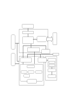
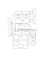
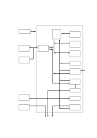
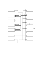
1.3 Main PCB 1.3.1 CPU Core Fig. 2.5 shows the ASIC circuit block on the main PCB. The CPU core is a Z80 which is driven with a clock frequency of 12.27 MHz. This frequency is made by dividing the source clock of 24.54 MHz into two in the oscillator circuit. The address bus is 16 bits and the data bus is 8 bits. The total memory space is 64 Kbytes. The CPU core access directly only the program ROM and the working S-RAM, and the DRAM through the DRAM control unit. NOTE: The ASIC has the functions above. Fig. 2.5 II-5
-
 1
1 -
2
-
3
-
4
-
5
-
6
-
7
-
8
-
9
-
10
-
11
-
12
-
13
-
14
-
15
-
16
-
 17
17 -
 18
18 -
 19
19 -
 20
20 -
 21
21 -
 22
22 -
 23
23 -
 24
24 -
 25
25 -
 26
26 -
 27
27 -
28
-
29
-
30
-
31
-
32
-
33
-
34
-
35
-
36
-
37
-
38
-
39
-
40
-
41
-
42
-
43
-
44
-
45
-
46
-
47
-
48
-
49
-
50
-
51
-
52
-
53
-
54
-
55
-
56
-
57
-
58
-
59
-
60
-
61
-
62
-
63
-
64
-
65
-
66
-
67
-
68
-
69
-
70
-
71
-
72
-
73
-
74
-
75
-
76
-
77
-
78
-
79
-
80
-
81
-
82
-
83
-
84
-
85
-
86
-
87
-
88
-
89
-
90
-
91
-
92
-
93
-
94
-
95
-
96
-
97
-
98
-
99
-
100
-
101
-
102
-
103
-
104
-
105
-
106
-
107
-
108
-
109
-
110
-
111
-
112
-
113
-
114
-
115
-
116
-
117
-
118
-
119
-
120
-
121
-
122
-
123
-
124
-
125
-
126
-
127
-
128
-
129
-
130
-
131
-
132
-
133
-
134
-
135
-
136
-
137
-
138
-
139
-
140
-
141
-
142
-
143
-
144
-
145
-
146
-
147
-
148
-
149
-
150
-
151
-
152
-
153
-
154
 |
 |

II-5
1.3
Main PCB
1.3.1
CPU Core
<HL-720>
Fig. 2.5 shows the ASIC circuit block on the main PCB.
The CPU core is a Z80 which is driven with a clock frequency of 12.27 MHz. This
frequency is made by dividing the source clock of 24.54 MHz into two in the
oscillator circuit. The address bus is 16 bits and the data bus is 8 bits. The total
memory space is 64 Kbytes.
The CPU core access directly only the program ROM
and the working S-RAM, and the DRAM through the DRAM control unit.
NOTE:
The ASIC has the functions above.
Fig. 2.5