Brother International HL-720 Service Manual - Page 56
Base Plate Assy, Fig. 3.8, Panel sensor PCB Assy, See III-5 .
 |
View all Brother International HL-720 manuals
Add to My Manuals
Save this manual to your list of manuals |
Page 56 highlights
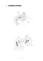
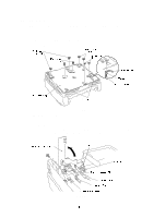
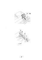
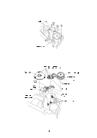
3.7 Base Plate Assy NOTE Prior to turning the printer upside-down, drum unit should be removed from the printer. (1) Turn the printer upside down. (2) Remove the four M4 and four M3 tapping screws. (3) Lift out the base plate assy and remove the grounding screw. Fig. 3.8 3.8 Panel sensor PCB Assy (1) Remove the screw securing the panel sensor PCB assy. (Remove the part A from under the main shield) (2) Disconnect the seven connectors from the PCB (The three connectors have already disconnected at the disassembling scanner unit. See page, III-5 ). Fig. 3.9
-
 1
1 -
2
-
3
-
4
-
5
-
6
-
7
-
8
-
9
-
10
-
11
-
12
-
13
-
14
-
15
-
16
-
17
-
18
-
19
-
20
-
21
-
22
-
23
-
24
-
25
-
26
-
27
-
28
-
29
-
30
-
31
-
32
-
33
-
34
-
35
-
36
-
37
-
38
-
39
-
40
-
41
-
42
-
43
-
44
-
45
-
46
-
47
-
48
-
49
-
50
-
 51
51 -
 52
52 -
 53
53 -
 54
54 -
 55
55 -
 56
56 -
 57
57 -
 58
58 -
 59
59 -
 60
60 -
 61
61 -
62
-
63
-
64
-
65
-
66
-
67
-
68
-
69
-
70
-
71
-
72
-
73
-
74
-
75
-
76
-
77
-
78
-
79
-
80
-
81
-
82
-
83
-
84
-
85
-
86
-
87
-
88
-
89
-
90
-
91
-
92
-
93
-
94
-
95
-
96
-
97
-
98
-
99
-
100
-
101
-
102
-
103
-
104
-
105
-
106
-
107
-
108
-
109
-
110
-
111
-
112
-
113
-
114
-
115
-
116
-
117
-
118
-
119
-
120
-
121
-
122
-
123
-
124
-
125
-
126
-
127
-
128
-
129
-
130
-
131
-
132
-
133
-
134
-
135
-
136
-
137
-
138
-
139
-
140
-
141
-
142
-
143
-
144
-
145
-
146
-
147
-
148
-
149
-
150
-
151
-
152
-
153
-
154
 |
 |

3.7
Base Plate Assy
NOTE
Prior to turning the printer upside-down,
drum unit should be removed from the
printer.
(1)
Turn the printer upside down.
(2)
Remove the four M4 and four M3 tapping screws.
(3)
Lift out the base plate assy and remove the grounding screw.
Fig. 3.8
3.8
Panel sensor PCB Assy
(1)
Remove the screw securing the panel sensor PCB assy. (Remove the part A
from under the main shield)
(2)
Disconnect the seven connectors from the PCB (The three connectors have already
disconnected at the disassembling scanner unit.
See page, III-5 ).
Fig. 3.9