Brother International HL-720 Service Manual - Page 121
Caution, Loosen the other M3x10 screw securing the fixing unit cover.
 |
View all Brother International HL-720 manuals
Add to My Manuals
Save this manual to your list of manuals |
Page 121 highlights
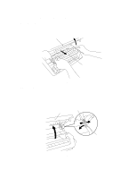
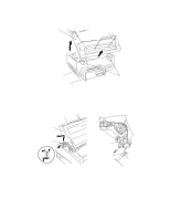
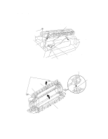
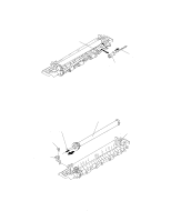
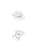
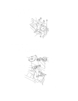
(5) Release the right side of the paper eject roller shaft. (6) Remove the four eject pinch rollers and the pinch springs from the fixing unit frame. Then, remove the pinch spring from each pinch roller. Paper eject roller shaft Pinch Spring Eject Pinch Roller Fig. 3.5b (7) Remove the M3x10 screw securing the electrode plate to remove the electrode plate from the fixing unit frame. (8) Loosen the other M3x10 screw securing the fixing unit cover. (9) Remove the heat roller. Then, remove the halogen heater lamp from the heat roller. Caution: Never touch the surface of the halogen heater lamp and the heat roller. Heat roller Halogen heater lamp (Blue 100V, Red 200V) Taptite M3x10 Taptite M3x10 Electrode plate Fig. 3.5c III-6
-
 1
1 -
2
-
3
-
4
-
5
-
6
-
7
-
8
-
9
-
10
-
11
-
12
-
13
-
14
-
15
-
16
-
17
-
18
-
19
-
20
-
21
-
22
-
23
-
24
-
25
-
26
-
27
-
28
-
29
-
30
-
31
-
32
-
33
-
34
-
35
-
36
-
37
-
38
-
39
-
40
-
41
-
42
-
43
-
44
-
45
-
46
-
47
-
48
-
49
-
50
-
51
-
52
-
53
-
54
-
55
-
56
-
57
-
58
-
59
-
60
-
61
-
62
-
63
-
64
-
65
-
66
-
67
-
68
-
69
-
70
-
71
-
72
-
73
-
74
-
75
-
76
-
77
-
78
-
79
-
80
-
81
-
82
-
83
-
84
-
85
-
86
-
87
-
88
-
89
-
90
-
91
-
92
-
93
-
94
-
95
-
96
-
97
-
98
-
99
-
100
-
101
-
102
-
103
-
104
-
105
-
106
-
107
-
108
-
109
-
110
-
111
-
112
-
113
-
114
-
115
-
 116
116 -
 117
117 -
 118
118 -
 119
119 -
 120
120 -
 121
121 -
 122
122 -
 123
123 -
 124
124 -
 125
125 -
 126
126 -
127
-
128
-
129
-
130
-
131
-
132
-
133
-
134
-
135
-
136
-
137
-
138
-
139
-
140
-
141
-
142
-
143
-
144
-
145
-
146
-
147
-
148
-
149
-
150
-
151
-
152
-
153
-
154
 |
 |

III-6
(5)
Release the right side of the paper eject roller shaft.
(6)
Remove the four eject pinch rollers and the pinch springs from the fixing unit frame.
Then, remove the pinch spring from each pinch roller.
Fig. 3.5b
(7)
Remove the M3x10 screw securing the electrode plate to remove the electrode plate
from the fixing unit frame.
(8)
Loosen the other M3x10 screw securing the fixing unit cover.
(9)
Remove the heat roller. Then, remove the halogen heater lamp from the heat roller.
Caution:
Never touch the surface of the halogen heater lamp and the heat roller.
Fig. 3.5c
Eject Pinch Roller
Paper eject roller shaft
Pinch Spring
Heat roller
Taptite M3x10
Taptite M3x10
Electrode plate
Halogen heater lamp
(Blue 100V, Red 200V)