Brother International HL-720 Service Manual - Page 124
PCB must not be lifted up by the harnesses.
 |
View all Brother International HL-720 manuals
Add to My Manuals
Save this manual to your list of manuals |
Page 124 highlights
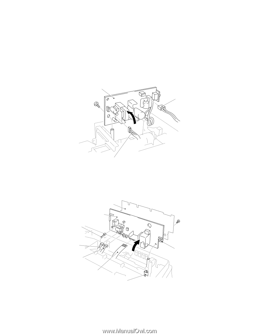
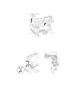
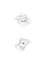
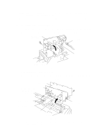
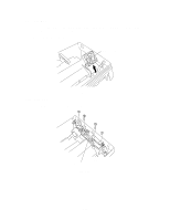
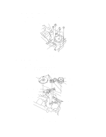
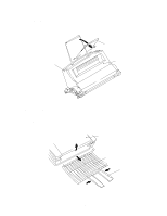
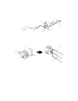
NOTE1: When reassembling, the connectors must be inserted fully into the PCB and the PCB must not be lifted up by the harnesses. NOTE2: The connectors should be inserted by matching the housing color and the number of pins. 3.9 Low-Voltage Power Supply PCB Assy (1) Remove the screw securing the low-voltage power supply PCB assy and lift the PCB. (2) Disconnect the two connectors from the component side of the PCB. Low-voltage power supply PCB assy Heater harness (CN1) LV harness (CN101) Fig. 3.10 3.10 High-voltage Power Supply PCB Assy (1) Remove the screw securing the high-voltage power supply PCB assy and lift the PCB. (2) Disconnect the four connectors from the PCB. Insulation sheet High-voltage power supply PCB assy Drum ground PCB harness (P4) Fan motor harness (P2) Erase lamp harness (P3) Density volume HV Flat cable (P1) Density dial Fig. 3.11 NOTE: When reassembling, the density volume adjuster knob must be fitted into the cutout side of the density dial. III-9
-
 1
1 -
2
-
3
-
4
-
5
-
6
-
7
-
8
-
9
-
10
-
11
-
12
-
13
-
14
-
15
-
16
-
17
-
18
-
19
-
20
-
21
-
22
-
23
-
24
-
25
-
26
-
27
-
28
-
29
-
30
-
31
-
32
-
33
-
34
-
35
-
36
-
37
-
38
-
39
-
40
-
41
-
42
-
43
-
44
-
45
-
46
-
47
-
48
-
49
-
50
-
51
-
52
-
53
-
54
-
55
-
56
-
57
-
58
-
59
-
60
-
61
-
62
-
63
-
64
-
65
-
66
-
67
-
68
-
69
-
70
-
71
-
72
-
73
-
74
-
75
-
76
-
77
-
78
-
79
-
80
-
81
-
82
-
83
-
84
-
85
-
86
-
87
-
88
-
89
-
90
-
91
-
92
-
93
-
94
-
95
-
96
-
97
-
98
-
99
-
100
-
101
-
102
-
103
-
104
-
105
-
106
-
107
-
108
-
109
-
110
-
111
-
112
-
113
-
114
-
115
-
116
-
117
-
118
-
 119
119 -
 120
120 -
 121
121 -
 122
122 -
 123
123 -
 124
124 -
 125
125 -
 126
126 -
 127
127 -
 128
128 -
 129
129 -
130
-
131
-
132
-
133
-
134
-
135
-
136
-
137
-
138
-
139
-
140
-
141
-
142
-
143
-
144
-
145
-
146
-
147
-
148
-
149
-
150
-
151
-
152
-
153
-
154
 |
 |