Brother International HL-720 Service Manual - Page 122
Never touch the inside of the scanner unit or the mirror when disassembling or
 |
View all Brother International HL-720 manuals
Add to My Manuals
Save this manual to your list of manuals |
Page 122 highlights
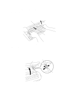
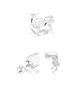
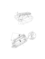
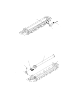
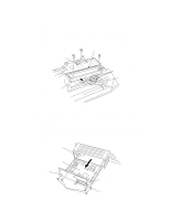
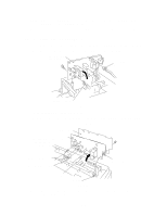
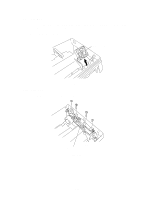
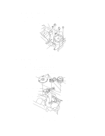
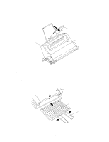
3.5 Scanner Unit (1) Remove the three screws. (2) Lift the scanner unit to obtain access to the panel sensor PCB. (3) Disconnect the three scanner unit connectors from the panel sensor PCB. (4) Remove the screw and disassemble the Toner sensor PCB from the Scanner unit. Mirror Toner sensor PCB Scanner unit S Seal sponge 1 Connectors (P2, P3, P9) Panel sensor PCB Fig. 3.6 NOTE: Never touch the inside of the scanner unit or the mirror when disassembling or reassembling. If there is any dirt or dust on the mirror, blow it off. 3.6 Main PCB Assy (1) Remove the four screws securing the main PCB holder to the back of the printer. (2) Grasp the hooks at the left and right ends of the PCB holder and draw out the main PCB assy. Rail Main PCB assy Hook Screws I/F Shield assy Fig. 3.7 Hook III-7
-
 1
1 -
2
-
3
-
4
-
5
-
6
-
7
-
8
-
9
-
10
-
11
-
12
-
13
-
14
-
15
-
16
-
17
-
18
-
19
-
20
-
21
-
22
-
23
-
24
-
25
-
26
-
27
-
28
-
29
-
30
-
31
-
32
-
33
-
34
-
35
-
36
-
37
-
38
-
39
-
40
-
41
-
42
-
43
-
44
-
45
-
46
-
47
-
48
-
49
-
50
-
51
-
52
-
53
-
54
-
55
-
56
-
57
-
58
-
59
-
60
-
61
-
62
-
63
-
64
-
65
-
66
-
67
-
68
-
69
-
70
-
71
-
72
-
73
-
74
-
75
-
76
-
77
-
78
-
79
-
80
-
81
-
82
-
83
-
84
-
85
-
86
-
87
-
88
-
89
-
90
-
91
-
92
-
93
-
94
-
95
-
96
-
97
-
98
-
99
-
100
-
101
-
102
-
103
-
104
-
105
-
106
-
107
-
108
-
109
-
110
-
111
-
112
-
113
-
114
-
115
-
116
-
 117
117 -
 118
118 -
 119
119 -
 120
120 -
 121
121 -
 122
122 -
 123
123 -
 124
124 -
 125
125 -
 126
126 -
 127
127 -
128
-
129
-
130
-
131
-
132
-
133
-
134
-
135
-
136
-
137
-
138
-
139
-
140
-
141
-
142
-
143
-
144
-
145
-
146
-
147
-
148
-
149
-
150
-
151
-
152
-
153
-
154
 |
 |
